Button switches

A switch and button technology, applied in the field of structure, can solve problems such as poor contact, lack of operation feeling, and affecting operation feeling

Inactive Publication Date: 2004-09-22
ALPS ALPINE CO LTD
View PDF1 Cites 5 Cited by
  • Summary
  • Abstract
  • Description
  • Claims
  • Application Information

AI Technical Summary

Problems solved by technology

[0012] Therefore, there is a problem that the position of the rubber spring 35 in the housing wall portion 31b is shifted, which may cause the end of the rubber spring 35 to be pressed, which affects the operating feeling (operation snapping), or dust enters the contact from the gap G. internal, resulting in poor contact
In addition, when the outer peripheral edge portion 35c of...

Method used


Image

  • Button switches
  • Button switches
  • Button switches

Examples


Embodiment Construction

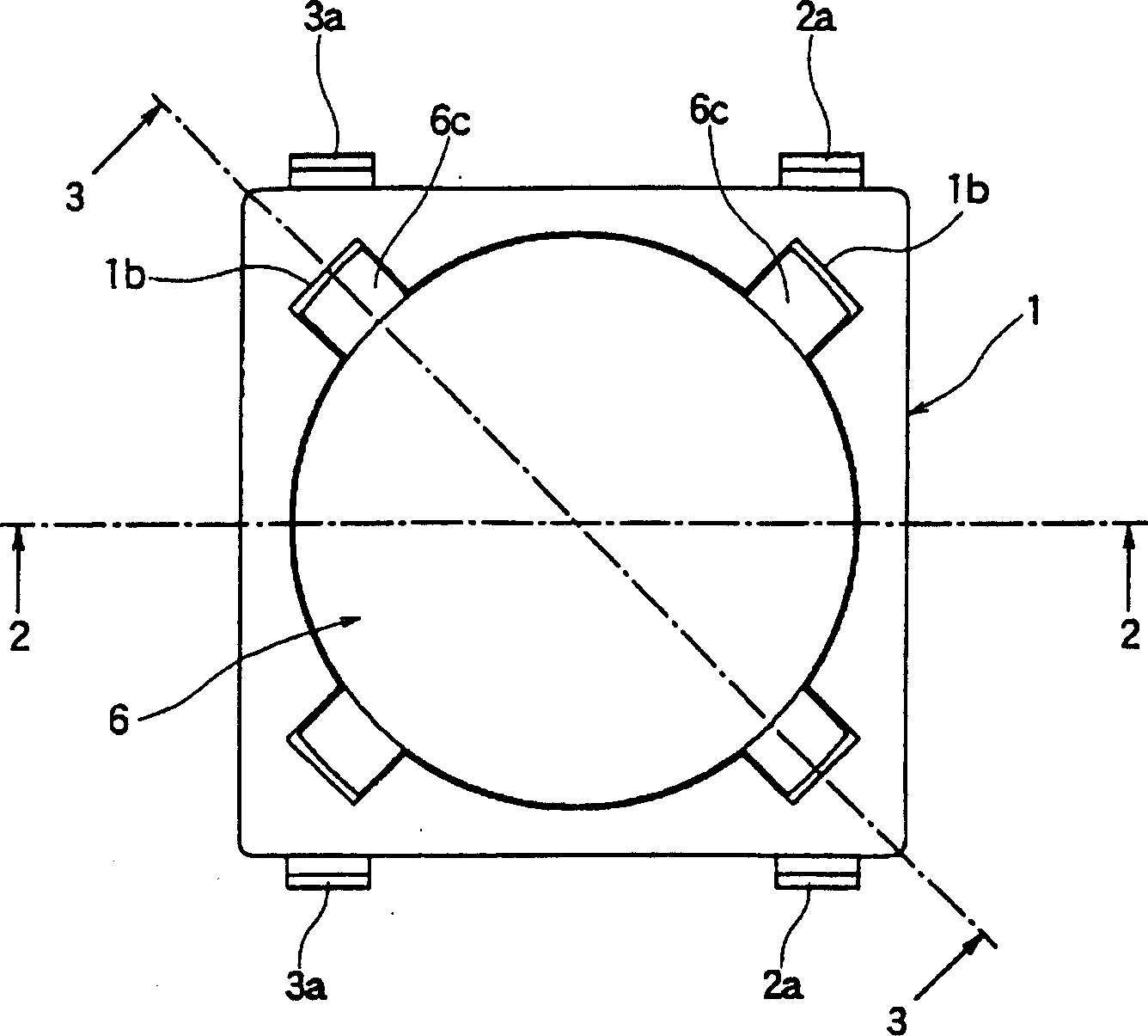
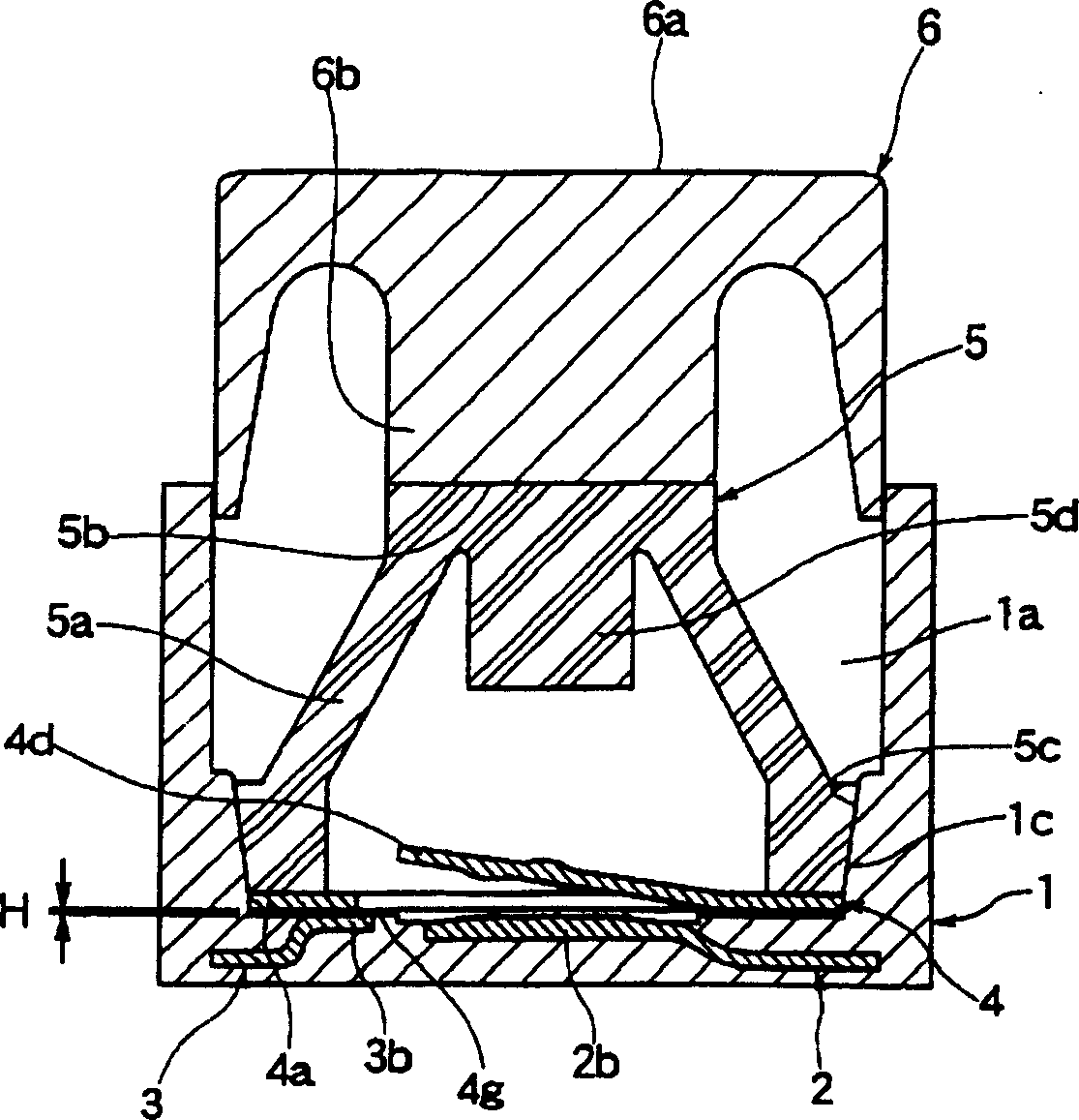
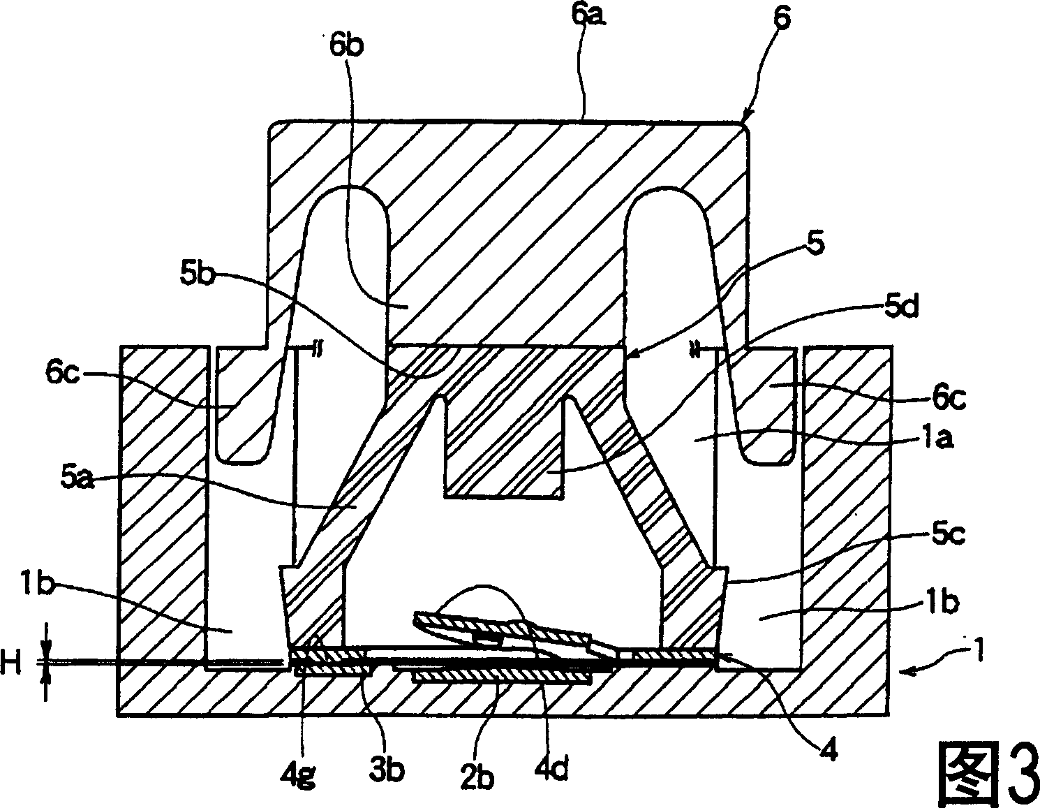
[0039] the following in Figure 1 to Figure 9 An embodiment of the push button switch of the present invention is shown in . figure 1 is the top view of the push button switch, figure 2 is along figure 1 The sectional view of line 2-2 in Figure 3 is along the figure 1 sectional view of the 3-3 line, Figure 4 is the top view of the shell, Figure 5 is the top view of the rubber spring, Image 6 is a sectional view of the rubber spring, Figure 7 is a top view of the movable contact, Figure 8 It is a sectional view of the movable contact. Figure 9 It is an explanatory diagram showing the dynamic force characteristic of the rubber spring.

[0040] The housing 1 is made of an insulating material such as synthetic resin into a rectangular box shape with an open top. A receiving portion 1a is formed in the opening of the housing 1, and a pair of fixed contacts 2, 3 formed of conductive metal materials such as brass are provided on the inner bottom of the receiving po...


PUM


Abstract

The present invention provides a push-button switch with high contact reliability, which provides a desired operation feeling, and prevents the invasion of dusts and the like to stabilize the contact state between a movable contact and a fixed contact when a rubber spring is pushed to perform the verse operation. The push-button switch is characterized in having: a housing having a housing part, fixed contacts fixed in the housing part, a movable contact arranged opposed to the fixed contacts, and a rubber spring having a lower end peripheral edge part in the holding part bendable skirt part provided in a space formed together with an upper end pressing surface part, and contacts/disconnects the movable contact to/from the fixed contact due to the bending of this skirt part. The lower end peripheral edge part of the rubber spring and opposed faces of a housing wall part of the housing 1 having this lower end peripheral edge part held therein are formed of inclined faces or arc faces each opening from the under face side toward the top face side.

Description

technical field [0001] The present invention relates to the structure of a push button switch used as an operation switch of various electronic devices, and particularly relates to the structure of a push button switch using a rubber spring as a flip spring. Background technique [0002] The structure of the conventional push button switch is known in which a movable contact facing the fixed contact and a rubber spring pressing the movable contact to the fixed contact side are arranged in the housing portion of the housing on which the fixed contact is mounted. , using the ejection force of the rubber spring to reset the operating stem (for example, refer to Patent Document 1). [0003] The structure of the conventional push button switch will be described in detail below with reference to the accompanying drawings. [0004] Fig. 11 is a plan view showing a conventional push button switch. Figure 12 It is a cross-sectional view showing a conventional push button switch. ...

Claims


Application Information

Patent Timeline
IPC IPC(8): H01H13/14H01H13/52
Inventor 岩隈晴海河原博幸早川和希
Owner ALPS ALPINE CO LTD
Why Eureka
Try Eureka