Inclined cutting saw with light projector

A technology of miter saw and light projection, applied in the direction of sawing machine device, attachment device of sawing machine, circular saw, etc., can solve the problems of reducing the efficiency and trouble of sawing workpiece W, etc.

Active Publication Date: 2004-09-29
HITACHI KOKI CO LTD
View PDF1 Cites 14 Cited by
  • Summary
  • Abstract
  • Description
  • Claims
  • Application Information

AI Technical Summary

Problems solved by technology

The user then rotates the turntable 720 and aligns the circular saw blade 721 with the line mark M2 or M3 before the user starts cutting the workpiece W. To align the saw blade 721 with the line mark M2 or M3, the user needs to go to the miter cut The back of the saw, and bend down or bend down to see the line mark M2 or M3 and the laser beam on the rear vertical plane of the workpiece W, which will be troublesome and reduce the efficiency of sawing the workpiece W

Method used


Image

  • Inclined cutting saw with light projector
  • Inclined cutting saw with light projector
  • Inclined cutting saw with light projector

Examples


Embodiment Construction

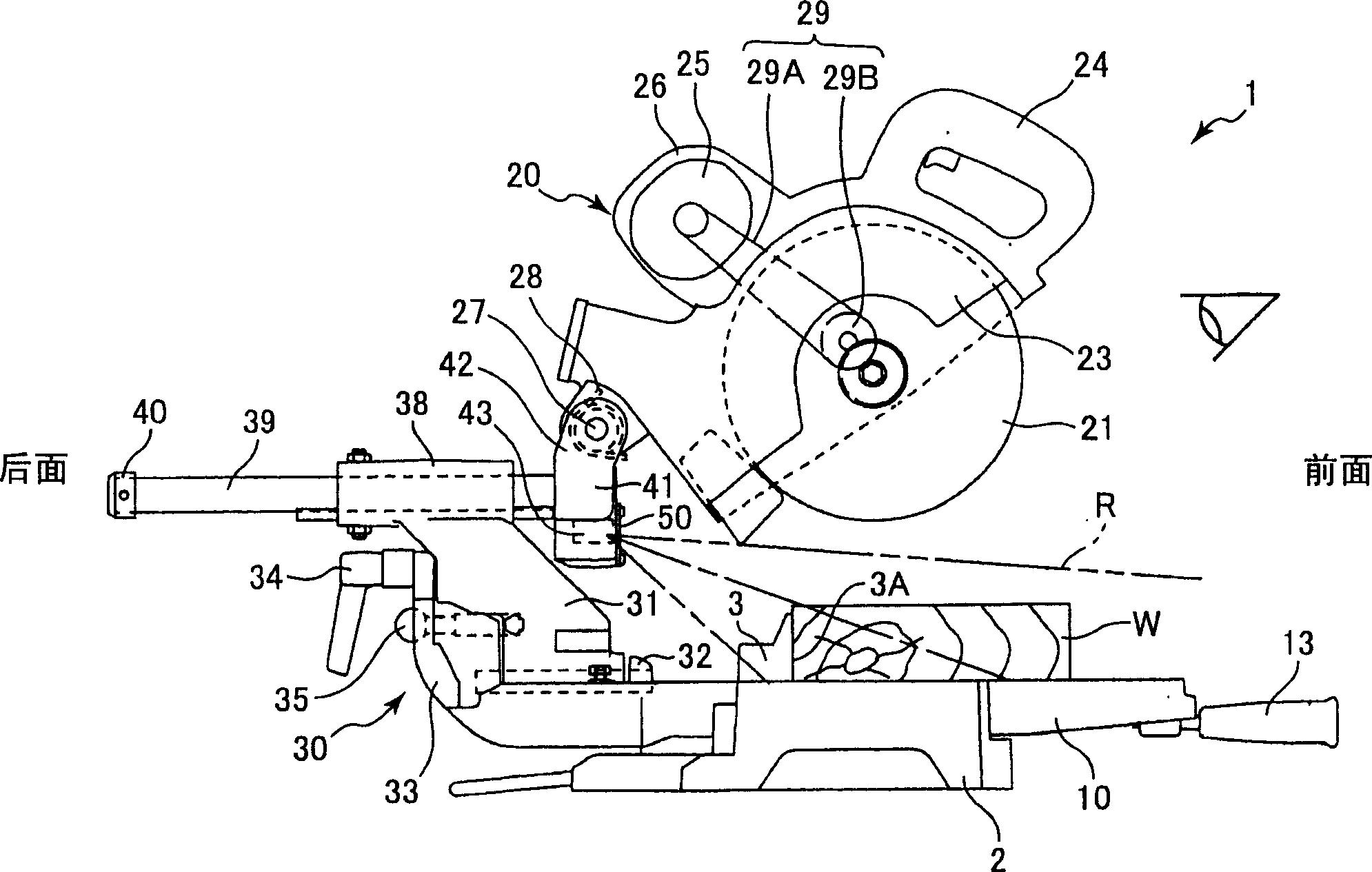
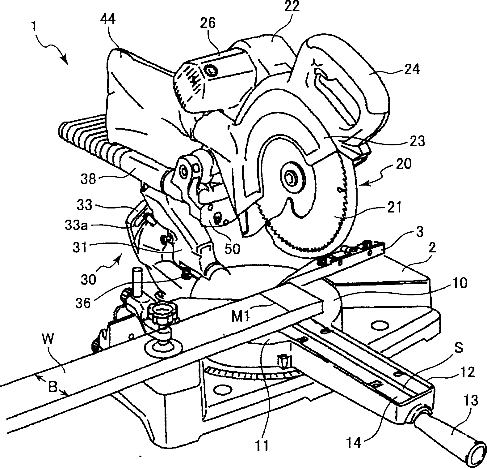
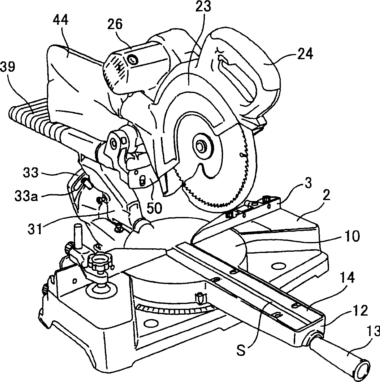
[0024] refer to Figure 1 to Figure 8 , a miter saw according to a first embodiment of the present invention will be described. The miter saw 1 generally includes a base 2 , a turntable 10 , a cutting device 20 and a supporting device 30 . The turntable 10 is rotatably mounted on the base 2, and is used to mount the workpiece on the base 2 together with the base 2. The cutting device 20 supports a circular saw blade 21 . The support device 30 extends from the turntable 10 for movably supporting the cutting device 20 at a position above the turntable 10 . The turntable 10 is embedded in the central part of the base 2 and can rotate on a horizontal plane. The upper surface of the turntable 10 is flush with the upper surface of the base 2 . Workpieces W such as wood and timber can be arranged on the upper surface of the base 2 and the turntable 10 , and the guardrail 3 extending along the diameter direction of the turntable 10 is fixed on the upper surface of the base 2 . Th...


PUM


Abstract

A miter saw including a base, a turntable, a cutting unit rotatably supporting a circular saw blade, and a support unit movably supporting the cutting unit at a position above the turntable. The support unit has a hinge formed with a recess in which a laser oscillator is accommodated. The laser oscillator emits a projected beam line on a surface of a workpiece W. The line indicates the position of a circular saw blade tip and its extension in a diametrical direction of the circular saw blade. The opening of the recess is closed with a cover that has an opening for allowing the laser beam to pass therethrough. The cover is positioned in confrontation with a fence on which the workpiece abuts for positioning. One surface of the cover is finished into a mirror surface which reflects a cutting line marker already marked on the workpiece and reflects a projected beam line.

Description

technical field [0001] The present invention relates to a miter saw, and more particularly, to a miter saw having a light projection device, such as a laser oscillator, for projecting a projected line on a workpiece representing the cutting position of the saw blade. Background technique [0002] Figure 17 shows a traditional miter saw, such as Figure 17 As shown, the miter saw includes: a base 702 , a guardrail 703 , a turntable 710 , a cutting device 720 , a supporting device 730 and a laser oscillator 751 . The turntable 710 is rotatably mounted on the base 702 for supporting the workpiece W thereon together with the base 702 . The guardrail 703 is fixed on the base 702 and extends across the turntable 710 . The guardrail 703 has a positioning surface against which the workpiece W abuts for positioning the workpiece W. As shown in FIG. The cutting device 720 has a circular saw blade 721 . The support device 730 movably supports the cutting device 720 at a position ab...

Claims


Application Information

Patent Timeline
IPC IPC(8): B27B9/00B23D59/00
CPCY10T83/828Y10T83/853B23D59/003Y10T83/839
Inventor 牛渡繁春今村隆一小泽隆史
Owner HITACHI KOKI CO LTD
Why Eureka
Try Eureka