Two stroke engine

An engine and two-stroke technology, which is applied in the direction of engine components, combustion engines, machines/engines, etc., can solve the problems that the demoulding is not easy, the demoulding slope is not large enough, etc.

Active Publication Date: 2004-09-29
ANDREAS STIHL AG & CO KG
View PDF1 Cites 4 Cited by
  • Summary
  • Abstract
  • Description
  • Claims
  • Application Information

AI Technical Summary

Problems solved by technology

However, when the cylinder is manufactured by die-casting, it is not easy to demould the overflow pipe groove designed as the ear canal, because the demoulding slope is not large enough

Method used


Image

  • Two stroke engine
  • Two stroke engine
  • Two stroke engine

Examples


Embodiment Construction

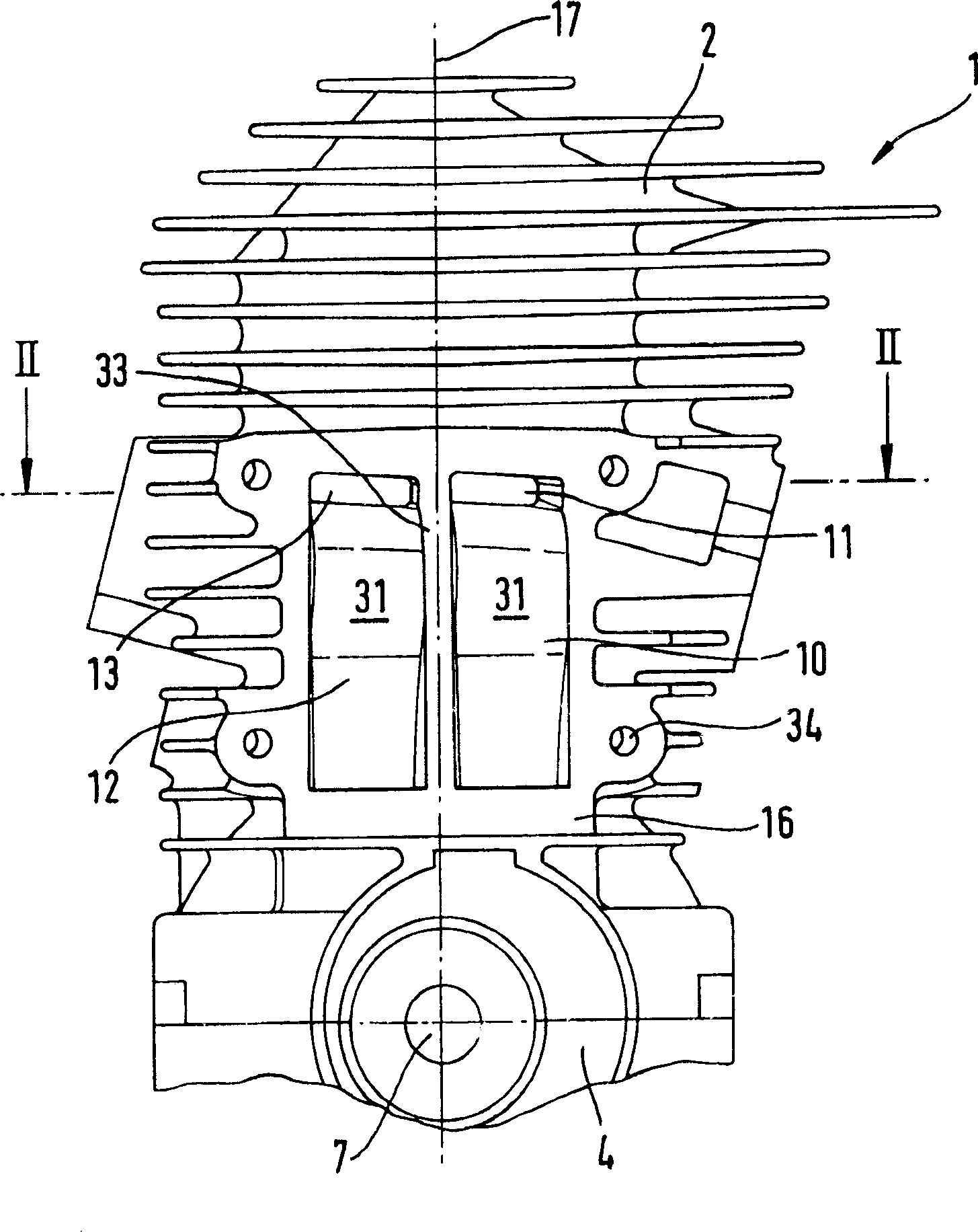
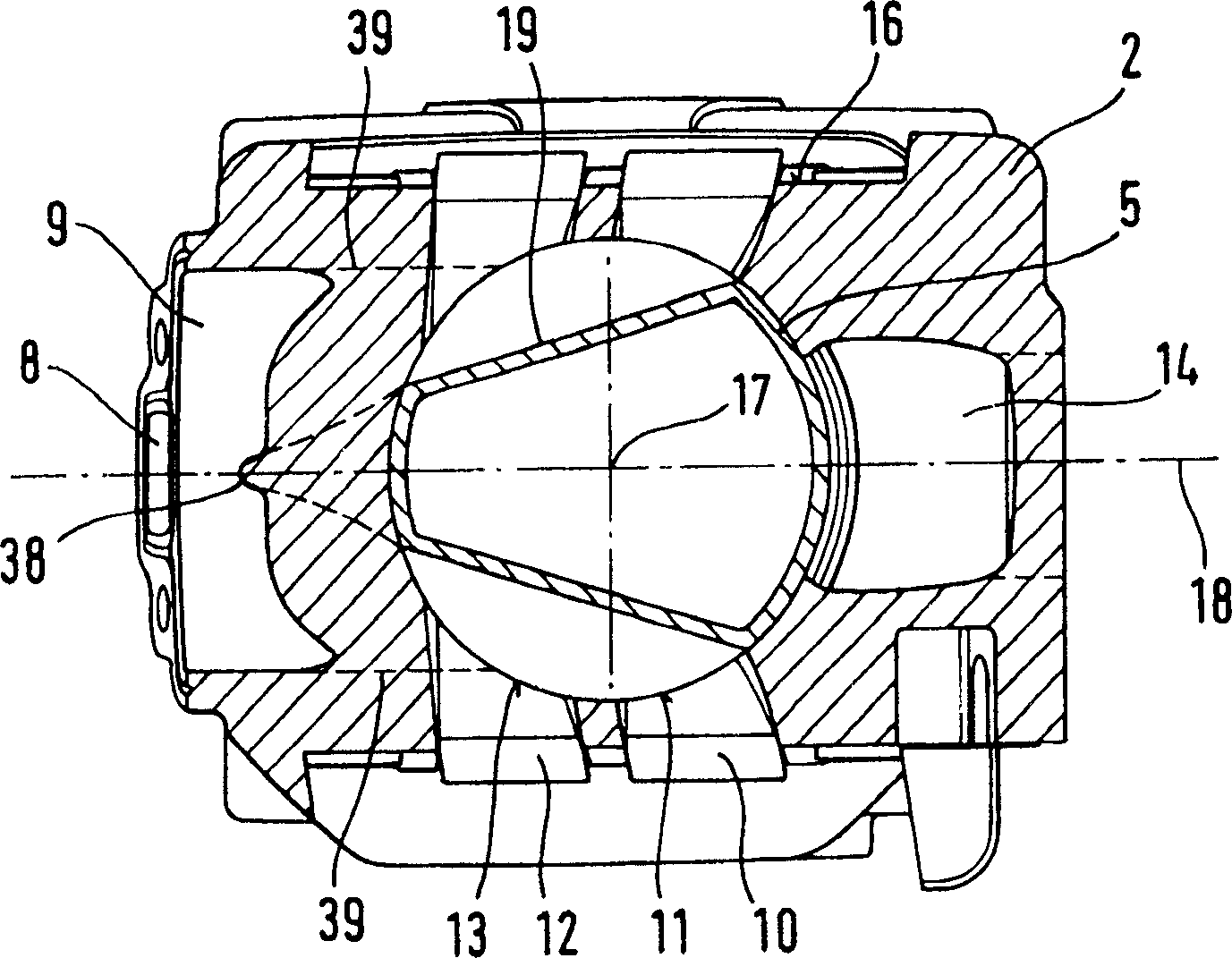
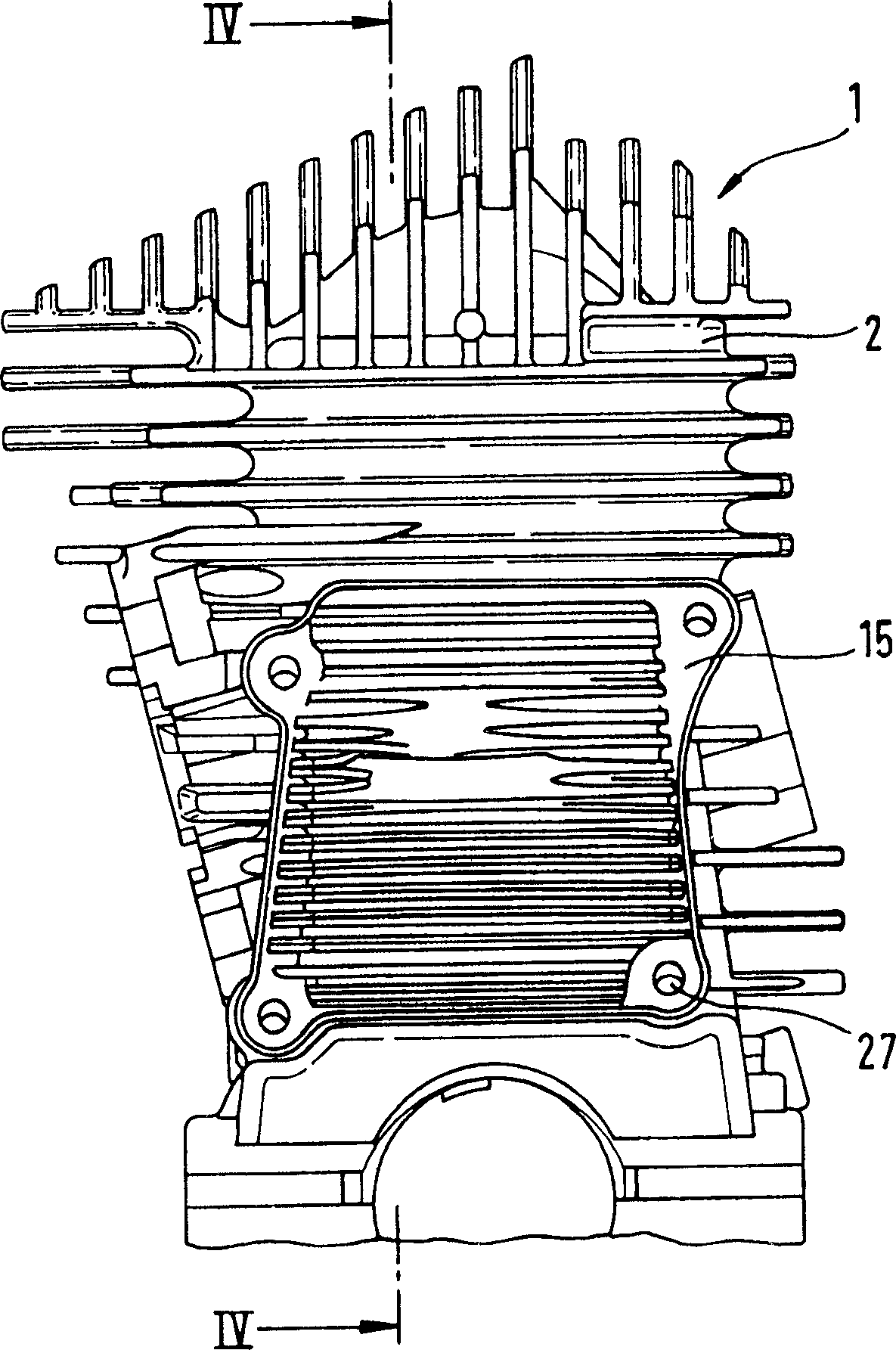
[0021] exist figure 1 The illustrated two-stroke engine 1 includes a cylinder 2 in which there is a Figure 4 Combustion chamber 3 is shown. like Figure 4 Combustion chamber 3 is delimited by piston 5 as shown. The piston 5 drives the cylinder supported in the crankcase 4 through a crank connecting rod. figure 1 The crankshaft 7 is shown. Crank connecting rod 6 is fixed on the piston 5 with a piston pin 21, in Figure 4 The piston is shown in dashed lines in . The crankcase 4 communicates with the combustion chamber 3 through the overflow pipe groove at the predetermined position of the piston 5 . The overflow pipe grooves 10 and 12 are open to the outside of the cylinder. The inner walls 31 of the overflow pipe grooves 10 and 12 are designed on the cylinder. The overflow pipe grooves 10 and 12 are designed as ear canals, so that the inner wall 31 runs curved in the direction of the cylinder longitudinal axis 17 . The overflow ducts 10 and 12 are surrounded on the ou...


PUM


Abstract

A two-cycle engine is provided that has a cylinder in which is formed a combustion chamber delimited by a reciprocating piston that via a connecting rod drives a crankshaft rotatably mounted in a crankcase. An inlet is provided for a supply of fuel into the crankcase, and an outlet leads out of the combustion chamber. In predetermined positions of the piston the crankcase communicates with the combustion chamber via at least one transfer channel. The cover is secured to a connecting flange of the cylinder, the cover closes off the transfer channel on an outer side of a cylinder, the connecting flange is inclined relative to the longitudinal axis of the cylinder by an angle that opens in a direction toward the crankcase.

Description

technical field [0001] The invention relates to a two-stroke engine of the type stated in the preamble of claim 1, in particular for use in a hand-guided tool such as a chainsaw, cutting machine or the like. Background technique [0002] From US 5,025,760 A a two-stroke engine is known, the overflow pipe groove facing the outside of the cylinder is closed with a cover. These transfer ducts are connected to the combustion chamber at a region of the cylinder parallel to the longitudinal axis of the cylinder and via a region approximately perpendicular to the longitudinal axis of the cylinder. The sudden turn of fluid in the overflow channel results in high resistance to flow. Less flow resistance can be achieved by designing the overflow pipe groove as an ear canal. However, when the cylinder is manufactured by die-casting, it is not easy to demould the overflow pipe groove designed as the ear canal, because the demoulding slope is not large enough. Contents of the inventi...

Claims


Application Information

Patent Timeline
Patent Type & Authority Applications(China)
IPC IPC(8): F02B63/02F02B75/02F02B75/16F02F1/22
CPCF02B75/16F02B63/02F02F1/22F02B2075/025
Inventor W·盖耶C·弗莱H·阿门德K·-M·乌尔J·施罗萨茨克
Owner ANDREAS STIHL AG & CO KG
Why Eureka
Try Eureka