
Dusting device of duster

A technology for vacuum cleaners and equipment, applied in the directions of vacuum cleaners, cleaning equipment, suction nozzles, etc., can solve the problems of weak suction and reduced cleaning performance.

Inactive Publication Date: 2004-10-27
LG ELECTRONICS INC
View PDF0 Cites 0 Cited by
  • Summary
  • Abstract
  • Description
  • Claims
  • Application Information

AI Technical Summary

Problems solved by technology

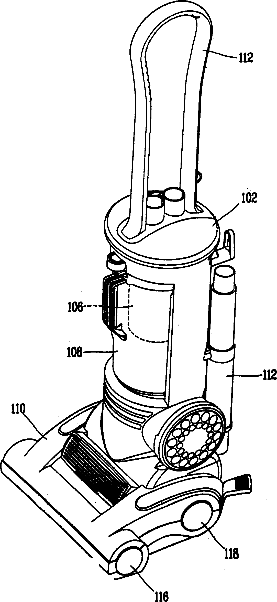
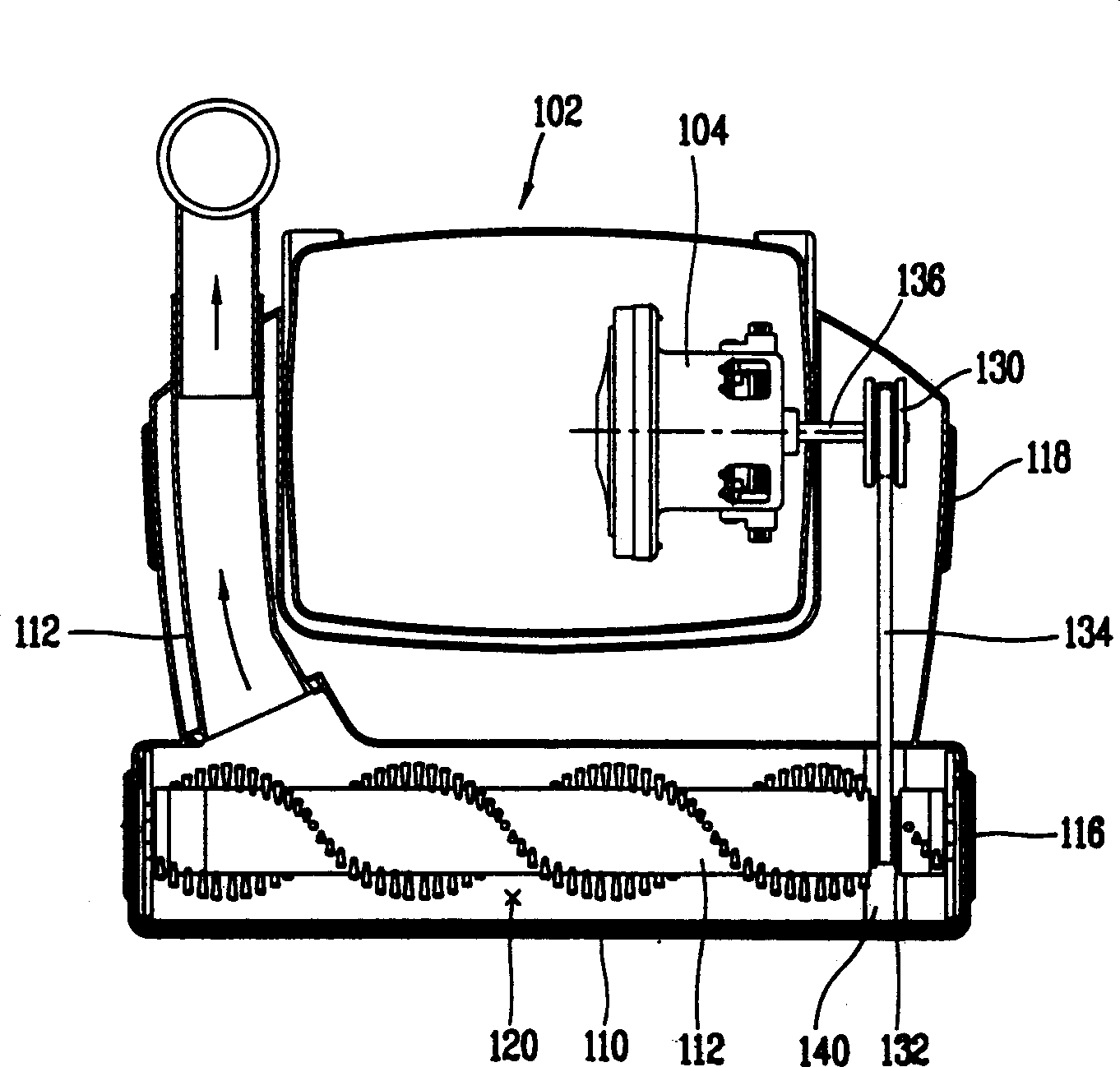
[0010] from figure 2 It can be seen that compared with the suction force of the left part of the dust suction port 120, the suction force of the right part of the dust suction port 120 is weaker. performance
[0011] In addition, since the belt cover 140 for protecting the belt 134 is installed on the right side of the suction port 120, the suction port at the part where the belt cover 140 is installed is closed, so the suction performance is also reduced.

Method used


Image

  • Dusting device of duster
  • Dusting device of duster
  • Dusting device of duster

Examples


Embodiment Construction

[0027] Reference will now be made in detail to the preferred embodiments of the invention, examples of which are illustrated in the accompanying drawings.

[0028] There are several embodiments of vacuum cleaner dusting apparatus according to the present invention, the most preferred one of which will now be described.

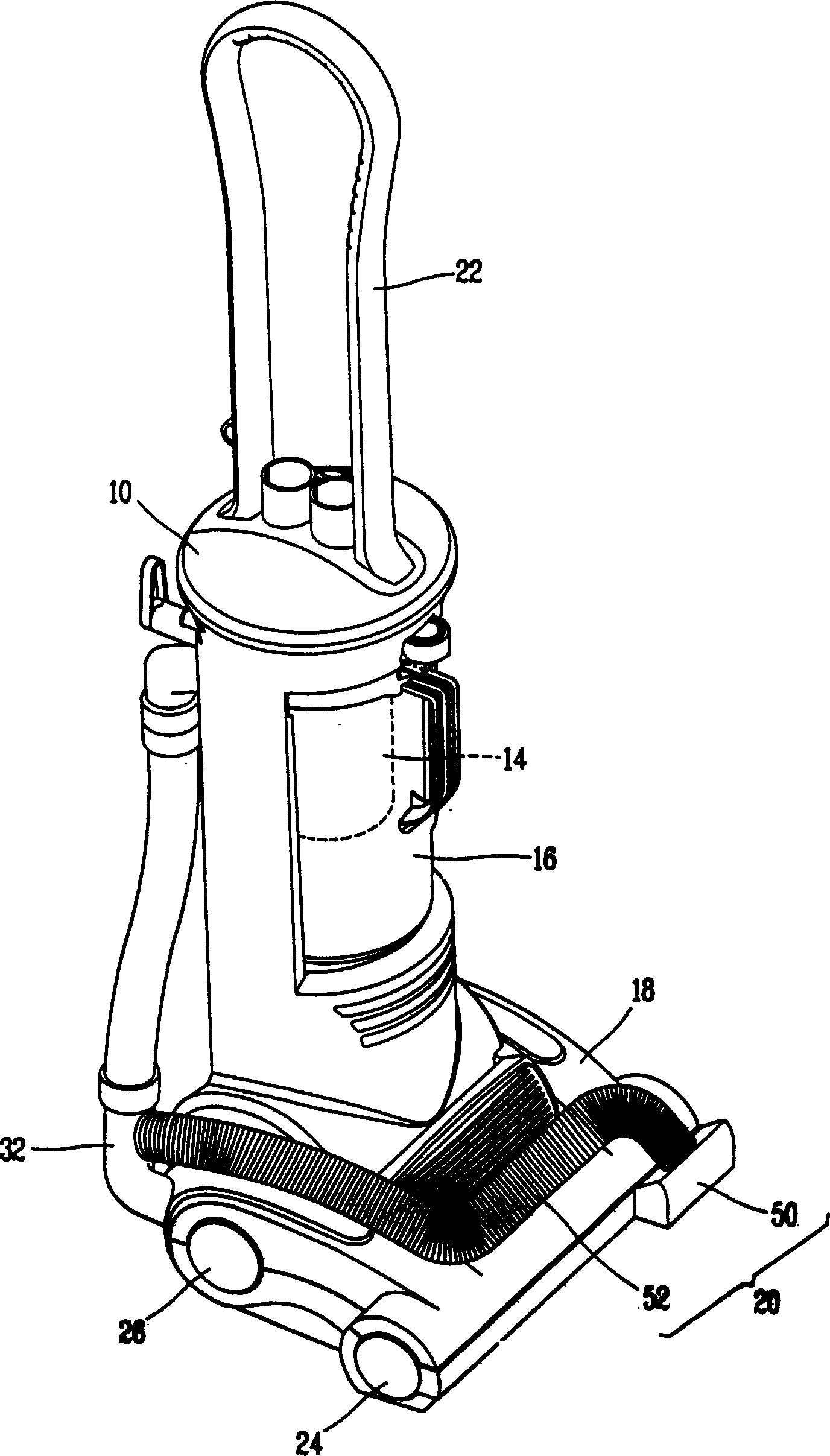
[0029] image 3 is a perspective view of an upright vacuum cleaner according to an embodiment of the present invention, Figure 4 is a cross-sectional view of an upright cleaner according to one embodiment of the present invention.

[0030] The upright vacuum cleaner according to the present invention includes a cleaner body 10 in a vertically upright state, a dust collector motor 12 inserted into the cleaner body 10 to generate suction, and a motor 12 placed on the dust suction side of the cleaner motor 12 to collect dust and dirt. filter 14, which dust and dirt are sucked by suction generated by the dust collection motor 12; a filter container 16 in which ...


PUM


Abstract

A suction apparatus of a cleaner includes: a suction motor inserted in a cleaner body and generating a suction force; a filter for collecting dust or filth sucked by a suction force generated fro the suction motor; a suction head connected to the filter by a suction pipe and sucking dust and filth on the floor by the suction force generated from the suction motor; and an auxiliary suction unit installed at the opposite side of a side where the suction pipe of the suction head is connected. A cleaning performance is enhanced by compensating a suction force at a portion where the suction force iA suction apparatus of a cleaner includes: a suction motor inserted in a cleaner body and generating a suction force; a filter for collecting dust or filth sucked by a suction force generated fro the

Description

technical field [0001] The present invention relates to a dust collection device of a vacuum cleaner, and more particularly to a dust collection device of a vacuum cleaner capable of improving dust collection performance by realizing concentrated dust collection in areas with relatively weak suction. Background technique [0002] figure 1 is a perspective view of an upright vacuum cleaner according to conventional technology, figure 2 is a cross-sectional view of an upright vacuum cleaner. [0003] The upright vacuum cleaner includes a cleaner body 102 in a vertical upright state, a suction motor 104 inserted into the cleaner body 102 and generating suction, and a filter 106 placed on the dust suction side of the dust suction motor 104 and collecting dust and dirt , these dust and dirt are sucked by the suction force produced by dust suction motor 104; Filter container 108 of filter 106 is installed therein; and a brush 112 rotatably mounted on the suction head and used ...

Claims


Application Information

Patent Timeline
Patent Type & Authority Applications(China)
IPC IPC(8): A47L9/00A47L5/12A47L5/30A47L9/02A47L9/04
CPCA47L5/30A47L9/02A47L9/00
Inventor 南贤植李映佑柳湖善郑春勉
Owner LG ELECTRONICS INC
Learn More