

Interlayer ventilated wall body
A wall and interlayer technology, applied in the field of building wall structure, can solve problems such as the limitation of application scope, and achieve the effect of reducing heat load
Inactive Publication Date: 2004-11-03
SHANGHAI INST OF TECH
View PDF0 Cites 18 Cited by
- Summary
- Abstract
- Description
- Claims
- Application Information
AI Technical Summary
Problems solved by technology
Due to the solar house wall, the building must have the form of a glass curtain wall in appearance, and the distinctive appearance of the building is wrapped in a glass shell. From an architectural point of view, its application range is limited.
Method used
View moreImage
Smart ImageViewing Examples

Examples
Embodiment Construction
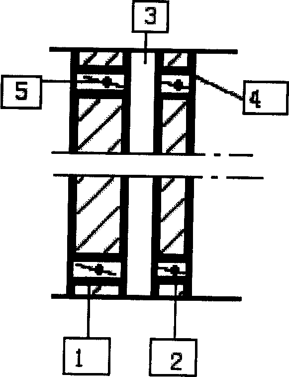
[0008] Depend on figure 1 As shown, the interlayer ventilated wall includes an outer wall 1 and an inner wall 2, and is characterized in that a ventilating air layer 3 is placed between the inner and outer walls, and the upper and lower parts of the inner and outer walls are provided with ventilation holes 4, and the ventilation holes are provided with To adjust the opening and closing device 5 of the airflow direction. The opening and closing device can be any parts that can achieve the opening and closing effect such as valves and baffles.
Login to View More PUM
 Abstract
The present invention relates to building wall structure, and is especially one sandwiched ventilation wall with ventilation structure inside the wall to reduce power consumption of the building. The sandwiched ventilation wall has ventilation air layer between the outer wall and the inner wall, and ventilating holes in the upper and lower parts of the outer wall and the inner wall and possessing on-off unit to control airflow direction. The present invention has positive significance in lowering heat load of building enclosing structure. Owing to the temperature difference between inside and outside room, the inlet air and outlet air is heat exchanged before intake or exhaust, and this utilizes the heat effectively to lower the heat load of wall. The novel wall has no influence on the look of building, and old building may be reformed via increasing sandwiched ventilation layer inside the original wall.
Description
technical field [0001] The invention relates to a building wall structure, in particular to a sandwich ventilated wall which reduces building energy consumption by adopting a ventilating structure inside the wall. Background technique [0002] As the main enclosure structure of a building, the wall's thermal insulation and insulation functions have an important impact on the building's energy consumption. In order to improve the thermal insulation capacity of the wall, the substantive technical characteristics of various technical measures currently used can be summarized as follows: 1. Increase the thickness of the wall; 2. Use an interlayer of heat-insulating materials in the wall; layer. At present, in the wall structure with an air layer, only the air layer in the wall of the sun room is used for air circulation replacement, and the rest are all closed air layers, and the wall with a sealed air layer has no energy-saving effect. ideal. The air replacement layer of the...
Claims
Login to View More Application Information
Patent Timeline
 Patent Type & AuthorityApplications(China)
IPC IPC(8): E04B2/00E04B2/28F24F13/068
Inventor冯劲梅王庆明
OwnerSHANGHAI INST OF TECH