
Unbalance signal complement method

A compensation method and a technology for balancing signals, which are applied in the direction of reducing unbalanced current interference, distribution line transmission systems, line transmission components, etc., and can solve the problems of unable to remove common-mode signal changes, unable to remove common-mode signals, and balance state damage, etc. question

Inactive Publication Date: 2004-11-03
ALPS ALPINE CO LTD
View PDF0 Cites 1 Cited by
  • Summary
  • Abstract
  • Description
  • Claims
  • Application Information

AI Technical Summary

Problems solved by technology

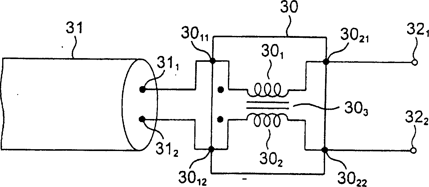
[0012] However, regarding the degree of imbalance to the balanced mode signal generated by the paired wire 31, when the length of the paired wire 31 that transmits the balanced mode signal changes, that is, the information terminal on the other side of the communication should be replaced. When the distance (length) to the information terminal on the other side changes via the double-strand wire 31, even if the length of the double-strand wire 31 that transmits the balanced mode signal does not change, it will cause the twist of the double-strand wire 31 due to changes in the surrounding environment. In the event of a change in construction status, etc., there will also be a change
[0013] However, since the structure of the above-mentioned known common choke coil 30 is fixed, if a state suitable for removing common-mode signals is set at a certain use time point, the above-mentioned state suitable for removing common-mode signals changes Afterwards, it is not possible to make the removal of the common-mode signal vary with this state change
That is to say, even if the common choke coil 30 can be set to a state suitable for removing the common-mode signal at a certain use time point, it may not be able to be set as usual after the use time point changes. Conditions suitable for removing common-mode signals, such that situations where effective removal of common-mode signals cannot occur
[0014] In contrast, the above-mentioned known Y-shaped circuit 40, since two capacitors 40 that will be connected in series 1 、40 2 The connection point (midpoint) of the so-called Y-shaped circuit suppressed with respect to a pair of line 40 3 、40 4 Therefore, even for the change of the length of the double-strand wire 41 or the change of the structural state of the double-strand wire 41, it can correspond within a certain range, but at the time when the transmission of the balanced mode signal starts points etc., due to the two capacitors 40 1 、40 2 The charge is in an uncharged state, so the two capacitors 40 1 、40 2 At the moment of charging, a pair of line 40 3 、40 4 The equilibrium state of , at which point the common-mode signal cannot be removed

Method used


Image

  • Unbalance signal complement method
  • Unbalance signal complement method
  • Unbalance signal complement method

Examples


Embodiment Construction

[0027] Embodiments of the present invention will be described below with reference to the drawings.

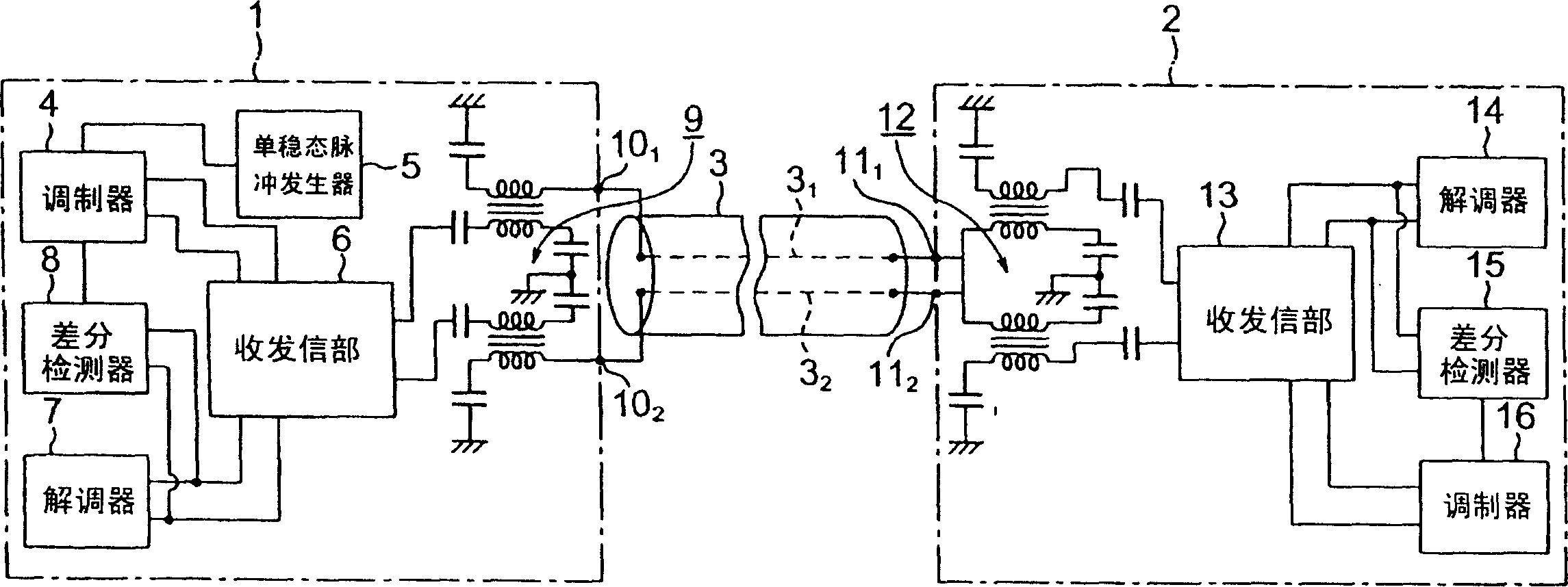
[0028] figure 1 Shown is an embodiment of the transmission signal system implementing the unbalanced signal compensation method in the present invention, figure 1 is a block diagram showing the structure of the main parts of the system.

[0029] Such as figure 1 As shown, the transmission signal system according to this embodiment consists of an information terminal (balanced data sender information terminal) 1 on one side, an information terminal (balanced data receiver information terminal) 2 on the other side, and an information terminal on this side. 1 and the information terminal 2 on the other side are composed of a pair of wires 3 that are combined.

[0030] In this case, the information terminal 1 on one side includes a modulator 4, a monostable pulse generator 5, a balanced data and detection signal transceiving section 6 having a transmitting section and a rece...


PUM


Abstract

Provided is a method of correcting an unbalanced signal by which a common mode signal superposed on a balanced signal can be removed according to changes in the length and structure of a pair electric wire. The method of correcting an unbalanced signal is used for a signal transmission system which transmits a balanced data signal through the pair electric wire for connecting terminals. Prior to transmitting the balanced data signal between the terminals, two single detection signals of the same phases are transmitted from a detection signal transmitting and receiving section of the terminal to the terminal through the pair electric wire. When a detection signal transmitting and receiving section of the terminal receives the two single detection signals through the pair electric wire, it forms a differential detection signal which indicates the signal unbalanced state of the pair electric wire based on the single detection signals and then transmits the formed differential detection signal put in phase with the pair electric wire to the terminal. When the detection signal transmitting and receiving section of the terminal receives the differential detection signal through the pair electric wire, it makes performs unbalance correction with respect to a balanced data signal transmitted to the pair electric wire based on the received differential detection signal.

Description

technical field [0001] The present invention relates to a method for compensating unbalanced signals, in particular to preventing the occurrence of the error transmitted through the double-strand wire when two or more terminals are combined through the double-strand wire and the balanced data signal is transmitted through the double-strand wire. This is an unbalanced signal compensation method in which noise is superimposed on a balanced data signal transmitted in a signal unbalanced state of a pair of wires. Background technique [0002] In general, as a signal transmission system using a pair of wires, it is known that two or more information terminals are combined on a double wire such as a power line that transmits alternating current, and any two information terminals among the two or more information terminals Using this pair of wires between them, a balanced data signal with a frequency much higher than that of the alternating current is superimposed on the alternatin...

Claims


Application Information

Patent Timeline
Patent Type & Authority Applications(China)
IPC IPC(8): H04B3/30H04B3/50H04B3/54
Inventor 樋口广一
Owner ALPS ALPINE CO LTD
Learn More