Semiconductor integrated circuit with function to detect state of stable oscillation

a technology of integrated circuits and oscillation states, applied in the direction of oscillation generators, generating/distributing signals, therapy, etc., can solve the problems of circuits running a risk of malfunction, oscillation waveforms may be easily disturbed, oscillation signals are not yet stable, etc., to achieve reliable detection of the state of stable oscillation

Inactive Publication Date: 2006-09-07
FUJITSU MICROELECTRONICS LTD
View PDF5 Cites 1 Cited by
  • Summary
  • Abstract
  • Description
  • Claims
  • Application Information

AI Technical Summary

Benefits of technology

[0015] According to at least one embodiment of the present invention, the amplitude of the oscillating signal is compared with the predetermined reference voltage to determine whether the amplitude of the oscillating signal is sufficiently large such that the oscillation is in a stable state. This makes it possible to reliably detect the state of stable oscillation without being affected by a shortening / elongating of the oscillation stabilization time due to differences in individual products and operation environments.

Problems solved by technology

Immediately after a semiconductor integrated circuit is powered on, the oscillating signal is not yet stable because the oscillation of the oscillator has just begun.
The amplitude of the oscillating signal is not sufficient during this waiting period before the stabilization of oscillation, and the oscillation waveform may easily be disturbed.
If the oscillating signal in such a state is used as a clock signal in the semiconductor integrated circuit, the circuit may be running a risk of suffering malfunction.
Accordingly, a small margin, if used, cannot guarantee reliable operation, and a large margin, if used for the purpose of securing sufficient reliability, results in a needless wait time being increased.

Method used


Image

  • Semiconductor integrated circuit with function to detect state of stable oscillation
  • Semiconductor integrated circuit with function to detect state of stable oscillation
  • Semiconductor integrated circuit with function to detect state of stable oscillation

Examples


Embodiment Construction

[0021] In the following, embodiments of the present invention will be described with reference to the accompanying drawings.

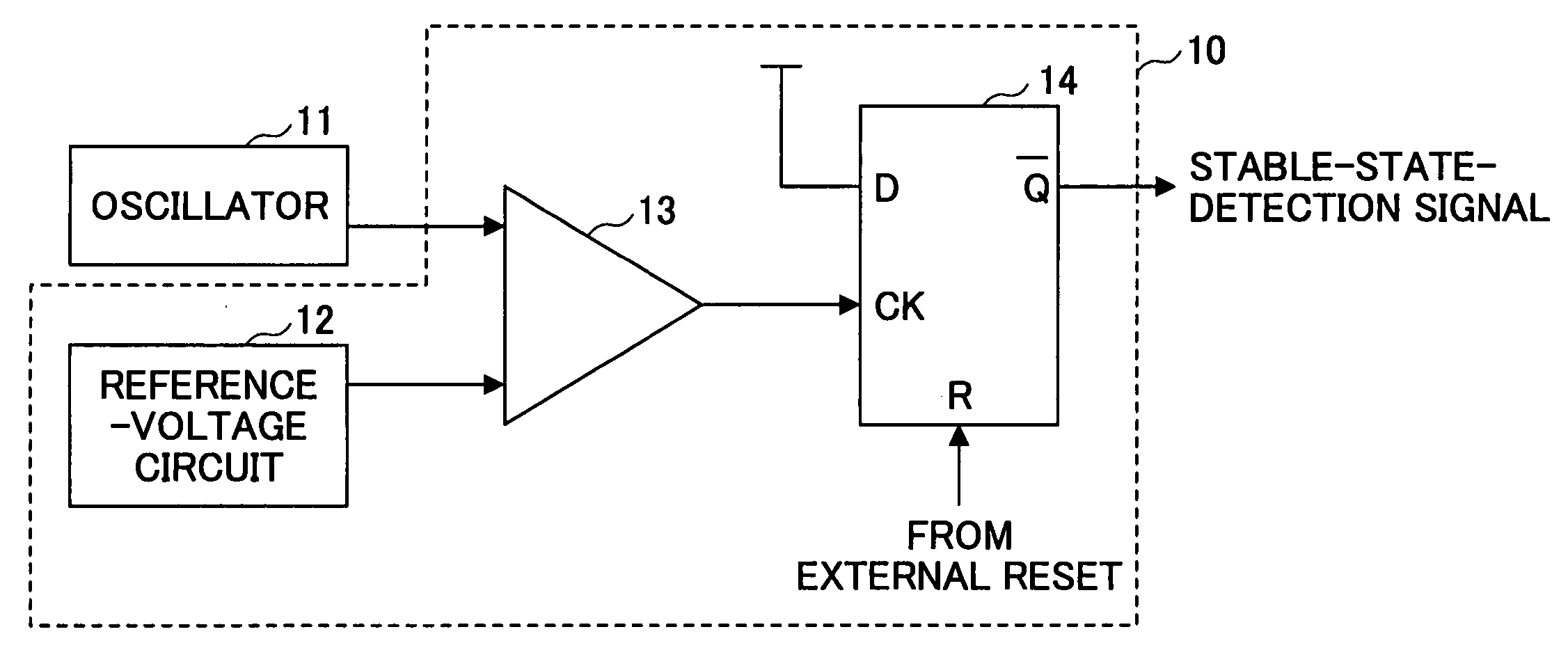
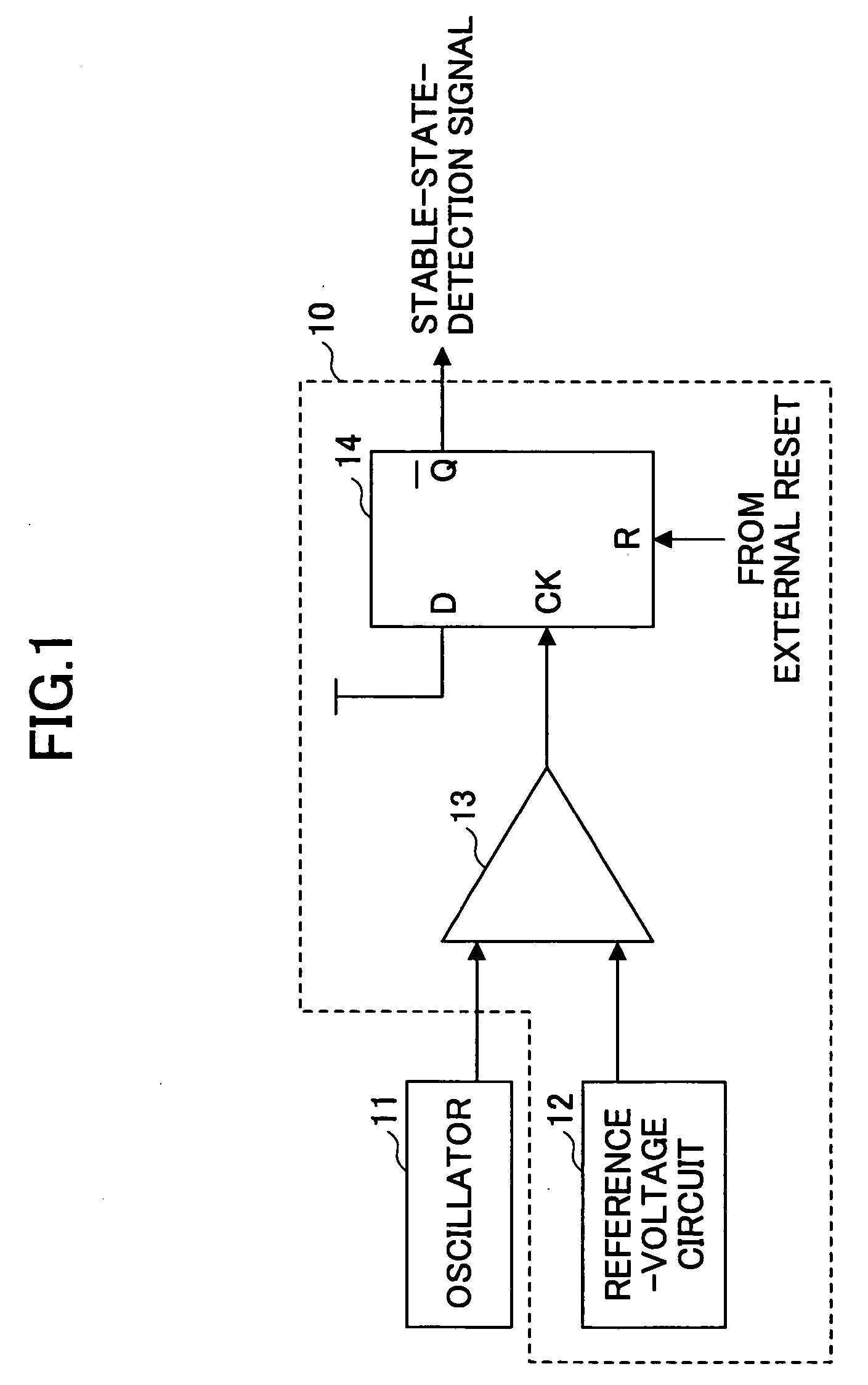
[0022]FIG. 1 is a drawing showing an example of the configuration of an oscillating-signal-stable-state detecting circuit according to the present invention. An oscillating-signal-stable-state detecting circuit 10 of FIG. 1 serves to determine whether the oscillating signal generated by an oscillator 11 has stabilized, and includes a reference-voltage circuit 12, a comparator 13, and a flip-flop 14.

[0023] The oscillator 11 may be a crystal oscillator, for example, and may be provided as a built-in component in the semiconductor integrated circuit to which the present invention is applied. If precision as high as that of a crystal oscillator is not required, a ceramic oscillator or the like may be used according to the application. Immediately after the semiconductor integrated circuit is powered on, the oscillating signal is not stable because the oscillation...


PUM


Abstract

A semiconductor integrated circuit includes a reference-voltage circuit configured to produce a predetermined reference voltage at an output node thereof, a comparator, coupled to a node to which an oscillating signal is supplied and to the output node of the reference-voltage circuit, to produce a result of comparison at an output node thereof, the result of comparison being made by comparing a voltage of the oscillating signal with the predetermined reference voltage, and a detection circuit coupled to the output node of the comparator to produce, in response to the result of comparison, a stable-state-detection signal indicating that the oscillating signal has an amplitude larger than the reference voltage.

Description

CROSS-REFERENCE TO RELATED APPLICATIONS [0001] The present application is based upon and claims the benefit of priority from the prior Japanese Patent Application No. 2005-062660 filed on Mar. 7, 2005, with the Japanese Patent Office, the entire contents of which are incorporated herein by reference. BACKGROUND OF THE INVENTION [0002] 1. Field of the Invention [0003] The present invention generally relates to semiconductor integrated circuits, and particularly relates to a semiconductor integrated circuit which operates based on an oscillating signal generated by an oscillator. [0004] 2. Description of the Related Art [0005] In many types of semiconductor integrated circuits, operations are controlled based on a clock signal that is generated by an oscillator. In order to generate a highly precise clock signal, a crystal oscillator is typically used. A crystal oscillator oscillates with highly precise oscillating frequency by utilizing a resonance effect of an external quartz resona...

Claims


Application Information

Patent Timeline
Patent Type & Authority Applications(United States)
IPC IPC(8): H03L7/085
CPCG06F1/04G06F1/24H03B5/06H03K5/19
Inventor MIHO, AKIRA
Owner FUJITSU MICROELECTRONICS LTD
Why Eureka
Try Eureka