Control unit for controlling DC/DC converter and DC/DC converter

a control unit and converter technology, applied in the direction of electrical equipment, emergency protective circuit arrangements, etc., can solve the problems of reducing affecting so as to reduce the cost, improve the efficiency of supply, and improve the effect of precision

Inactive Publication Date: 2007-06-21
FUJITSU LTD
View PDF0 Cites 1 Cited by
  • Summary
  • Abstract
  • Description
  • Claims
  • Application Information

AI Technical Summary

Benefits of technology

[0012] However, an input voltage of a non-isolated on-board power supply has tended to be diversified in recent years. This reflects various requirements. Namely, a wide range of input voltages is required in order to: improve efficiency in supply or reduce a cost by classifying commodities into groups associated with diverse input voltages; cope with a change in a voltage drop on wiring occurring when a power level is increased; and utilize an inexpensive isolated power supply whose output is low in precision.

Problems solved by technology

As a result, a protective fuse may be melted or the isolated power supply in the preceding stage may halt due to an overload.

Method used


Image

  • Control unit for controlling DC/DC converter and DC/DC converter
  • Control unit for controlling DC/DC converter and DC/DC converter
  • Control unit for controlling DC/DC converter and DC/DC converter

Examples


Embodiment Construction

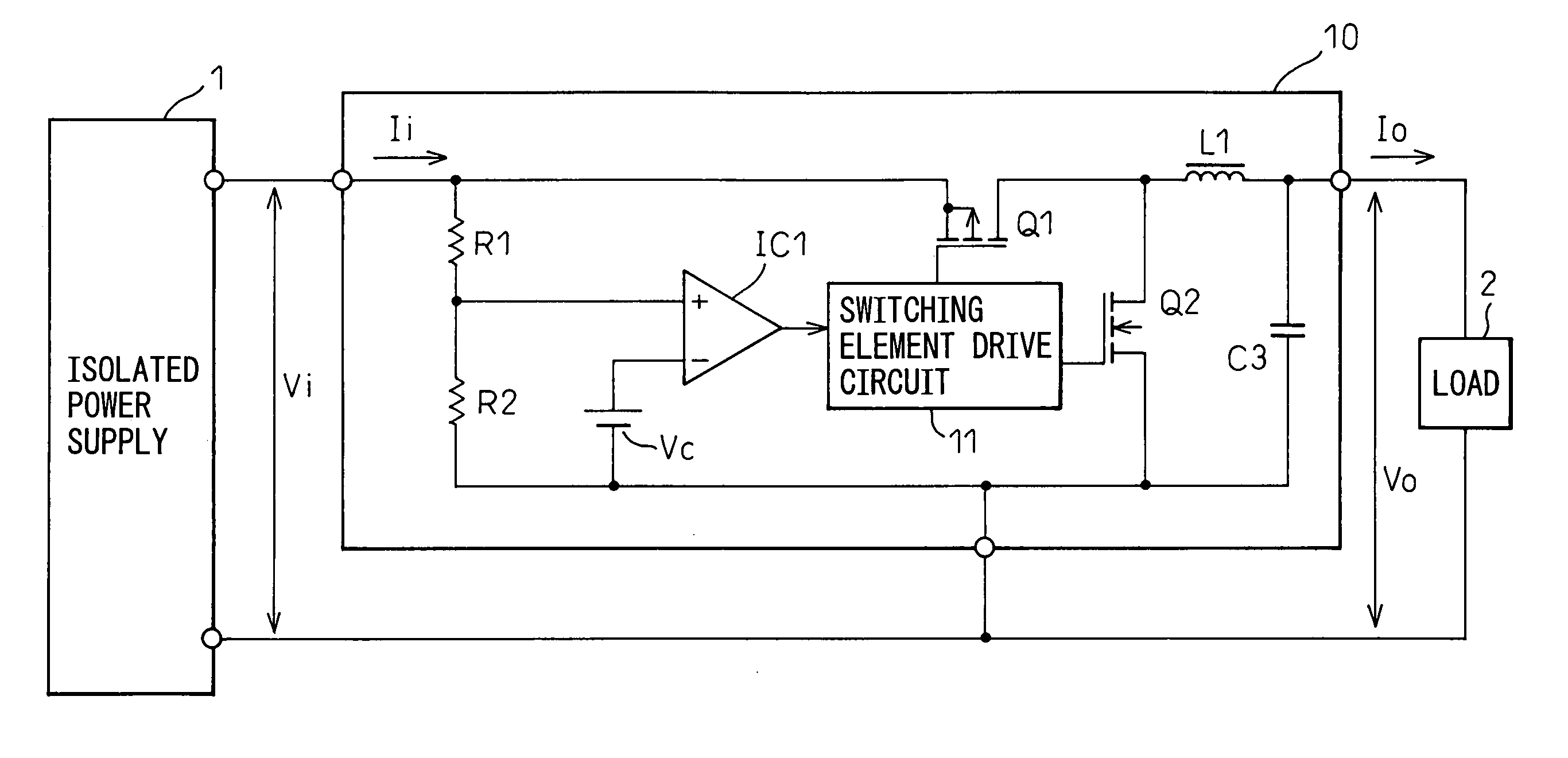
[0033] Preferred embodiments of the present invention will be described in detail below while referring to the attached figures. FIG. 6 shows the outline configuration of a non-isolated on-board power supply in accordance with an embodiment of the present invention.

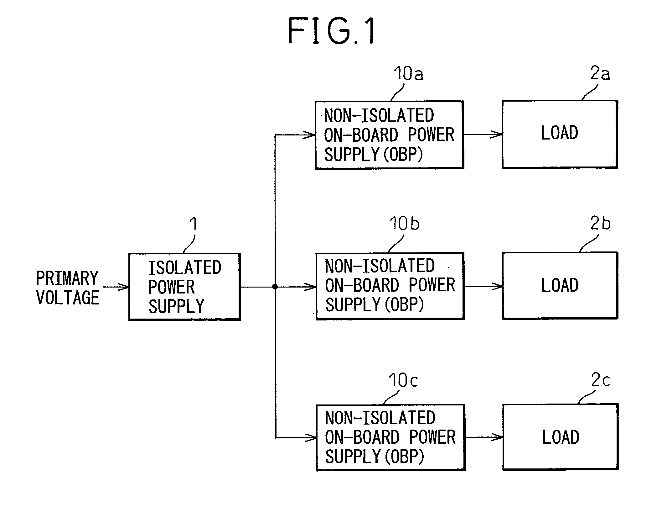
[0034] An isolated power supply 1 that transforms a primary voltage such as a mains voltage while insulating a primary side from a secondary side feeds dc power to a non-isolated on-board power supply 10. The non-isolated on-board power supply 10 converts the dc power into dc power of a predetermined voltage, and feeds the dc power to a load 2.

[0035] The non-isolated on-board power supply 10 includes switching elements Q1 and Q2, a switching element drive circuit 11 that turns on or off the switching elements alternately, and a smoothing LC filter composed of an inductor L1 and a capacitor C3. The switching element drive circuit 11 can adjust an output voltage Vo by varying a ratio of a time during which the switching e...


PUM


Abstract

The present invention is intended to prevent the flow of a large input current into a DC/DC converter, to which power is fed from a power supply, before a supply voltage delivered from the power supply reaches a rated output voltage. A control unit included in the DC/DC converter includes a steady state detection block that detects a condition in which an input voltage to be applied to the DC/DC converter has been stabilized, and inhibits the power feed from the DC/DC converter until the input voltage delivered from a power supply in a preceding stage is stabilized.

Description

CROSS-REFERENCE TO RELATED APPLICATION [0001] This application is based upon and claims the benefit of priority from the prior Japanese Patent Application No. 2005-363716, filed on Dec. 16, 2005, the entire contents of which are incorporated herein by reference. BACKGROUND OF THE INVENTION [0002] 1. Field of the Invention [0003] The present invention relates to a control unit for controlling a DC / DC converter and a DC / DC converter including the control circuit. More particularly, the present invention is concerned with a start control method for a non-isolated DC / DC converter that is applied to a power feed circuit that feeds power to a load from a non-isolated DC / DC converter, which is realized with a compact non-isolated on-board power supply or the like, disposed near the load so as to prevent a voltage drop caused by a wiring resistance. [0004] 2. Description of the Related Art [0005] In recent years, a power feed circuit that feeds power by a compact non-isolated on-board power...

Claims


Application Information

Patent Timeline
Patent Type & Authority Applications(United States)
IPC IPC(8): H02H7/122
CPCH02H7/1222
Inventor MIYAZAKI, TAKAHIRO
Owner FUJITSU LTD
Why Eureka
Try Eureka