Triangle polygon plotting device and triangle polygon plotting method

A technology for drawing devices and polygons, which is applied in the fields of filling planes with attributes, image data processing, 3D modeling, etc., and can solve the problems of large extra header information, increased H/W, and large amount of calculation in scan line update.

Inactive Publication Date: 2004-11-03
MITSUBISHI ELECTRIC CORP
View PDF0 Cites 3 Cited by
  • Summary
  • Abstract
  • Description
  • Claims
  • Application Information

AI Technical Summary

Problems solved by technology

Due to the relatively large amount of calculation for sub-pixel collection, the extra head

Method used


Image

  • Triangle polygon plotting device and triangle polygon plotting method
  • Triangle polygon plotting device and triangle polygon plotting method
  • Triangle polygon plotting device and triangle polygon plotting method

Examples


Embodiment approach 1

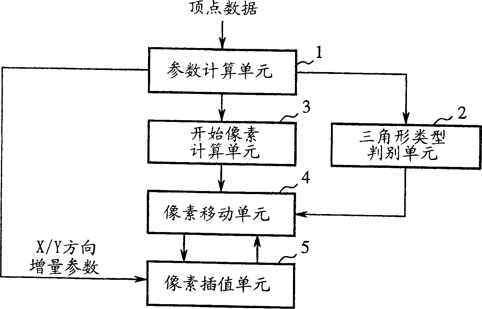
[0032] figure 2 It is a diagram showing the configuration of the triangular polygon drawing device according to Embodiment 1 of the present invention.

[0033] exist figure 2 Among them, 1 is the parameter calculation unit that calculates incremental parameters from the vertex data of the triangle polygon, 2 is the triangle type discrimination unit that divides the shape of the triangle polygon into 4 types from the parameter calculation unit 1, and 3 is the triangle type discrimination unit from the parameter calculation unit 1 The initial pixel calculation unit that starts to calculate the initial pixel, 4 is the pixel moving unit (pixel drawing unit) corresponding to the discrimination result of the triangle type discrimination unit 2 to move the pixel to the X direction or the Y direction, and 5 is the corresponding pixel moving unit 4 to interpolate the pixel value of the pixel interpolation unit (pixel rendering unit).

[0034] The operation is described below.

[0...

Embodiment approach 2

[0085] Image 6 is a diagram showing the configuration of a triangle polygon drawing device according to Embodiment 2 of the present invention. and figure 2 The same symbols refer to the same or equivalent structures.

[0086] exist Image 6 Among them, 6 is a pixel moving direction pre-determining unit (pixel drawing unit), which determines the moving direction of the pixel in advance by judging whether the pixel is inside or outside the triangular polygon.

[0087]The operation of this second embodiment is basically the same as that of the first embodiment, except that the moving direction of the pixel is determined in advance by calculating the value of the edge function in advance. That is to say, instead of performing the addition of the edge function and the addition of the pixel (such as the Z value) at the same time, the addition of the edge function can be processed in advance (for example, 1 clock pulse in advance), and it is possible to pre-determine whether to ...


PUM


Abstract

A triangular polygon drawing apparatus includes parameter calculating means 1 for calculating increment parameters from vertices V0 to V2 of a triangular polygon, triangle type determining means 2 for classifying the shape of the triangular polygon according to the direction and slope of a major edge of the triangular polygon so as to determine a moving direction in which pixels are to be moved, start pixel calculating means 3 for calculating various components of a start pixel, and pixel moving means 4 and pixel interpolating means 5 for generating pixels starting from the start pixel by interpolation with respect to a direction of an X axis and saving a generated pixel M that is placed inside the triangular polygon across the major edge for the first time, for generating pixels running from the major edge to a minor edge by interpolation so as to draw one scanline of said triangular polygon, and for generating a start pixel of the next scanline from the saved pixel M by interpolation with respect to a direction of a Y axis.

Description

technical field [0001] The present invention relates to a triangular polygon rendering device and a triangular polygon rendering method for decomposing a triangular polygon into pixels in the technical field of displaying an image as computer graphics on a display. Background technique [0002] Figure 1A It is a figure for explaining the conventional triangular polygon drawing method. This conventional triangular polygon drawing method is disclosed in the documents listed below, and generates pixels by repeatedly performing edge processing and spacing processing. [0003] <document> [0004] "Computer Graphics Principles and Practice Second Edition" ("Computer Graphics Principles and Practice Second Edition") pp.883-pp.885 [0005] James D. Foley, Andries van Dam, Steven K. Feiner, John F. Hughes [0006] The operation is described below. [0007] like Figure 1B As shown, the triangular polygon rendering method is divided into three types of processing: setting ...

Claims


Application Information

Patent Timeline
IPC IPC(8): G06T11/40
CPCG06T11/40G06T17/20
Inventor 加藤义幸鸟居晃
Owner MITSUBISHI ELECTRIC CORP
Why Eureka
Try Eureka