
Droplet deposition apparatus

A technology of deposition equipment and equipment, applied in printing, inking device, etc., can solve problems such as increasing machine size

Inactive Publication Date: 2004-12-08
XAAR TECH LTD
View PDF5 Cites 15 Cited by
  • Summary
  • Abstract
  • Description
  • Claims
  • Application Information

AI Technical Summary

Problems solved by technology

[0009] While this configuration is stable, it increases the size of the machine, so methods for smaller ink supply systems are needed

Method used


Image

  • Droplet deposition apparatus
  • Droplet deposition apparatus
  • Droplet deposition apparatus

Examples


Embodiment Construction

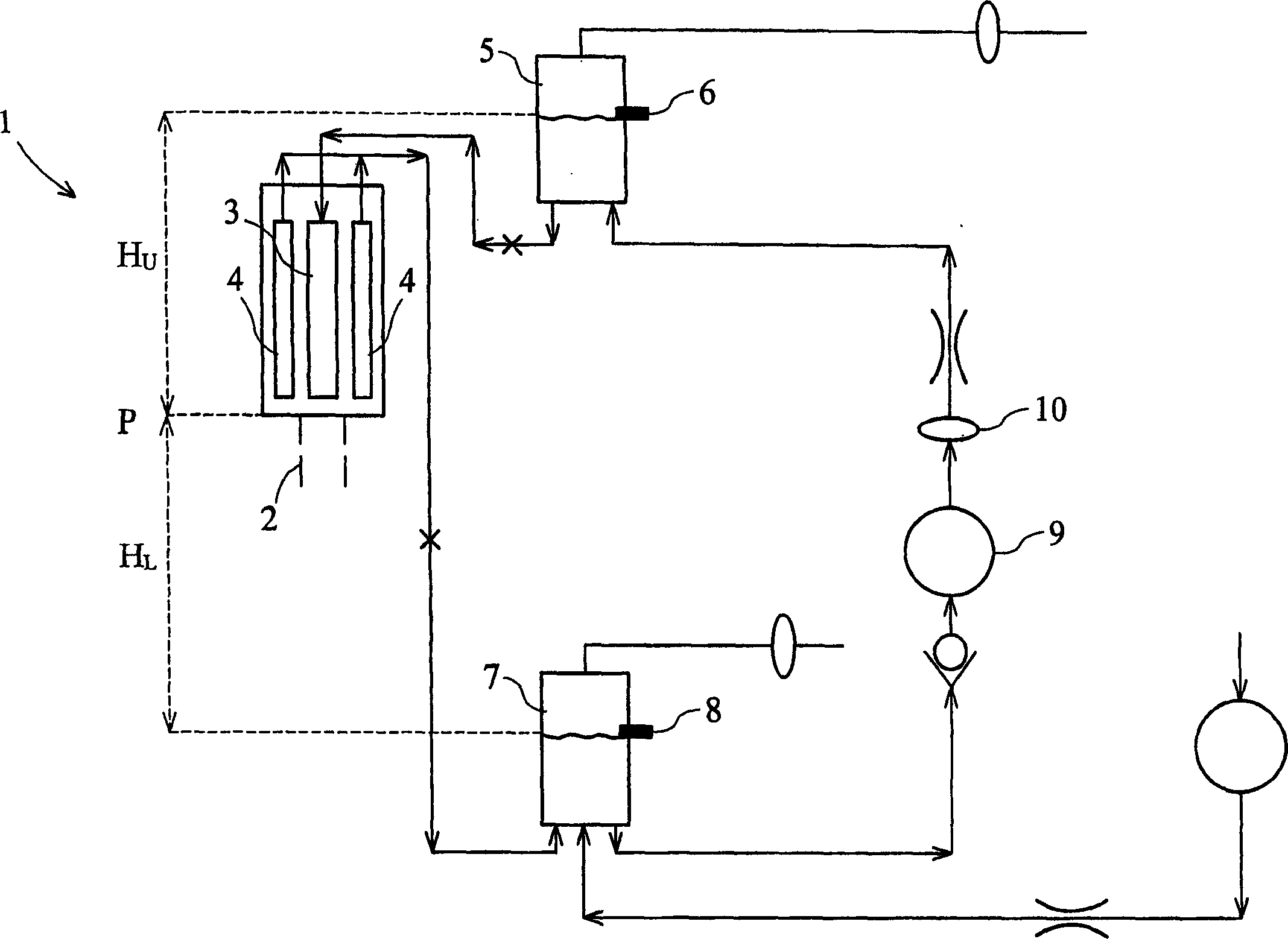
[0039] figure 1 A gravity-fed ink supply system according to the prior art. The print head 1 is capable of ejecting a liquid 2 from nozzles located on the lower side of the print head. The ink chambers have or discharge nozzles and are arranged in two parallel arrays, ink is supplied to the ink chambers from a central manifold 3, while un-ejected ink is expelled from the printhead using two outlet manifolds 4.

[0040] Ink is continuously supplied to the printhead from an upper reservoir 5 , the level of which is controlled by a level sensor 6 . The ink stream flow rate or flow rate is approximately ten times the maximum droplet or droplet ejection flow rate or flow rate. Due to the small size of the jetting chambers and the high pressure drop across them, achieving a slight negative pressure at the nozzle requires high pressure fluid flow into the printhead. This pressure is achieved by setting the pressure difference Hu, which is the difference between the height of the l...


PUM


Abstract

An ink supply system for a droplet deposition apparatus wherein the pressure at the nozzle is controlled by a remote point, said remote point being positioned in parallel with said print head. The flow restrictions in the printhead arm and the pressure control arm of the circuit being selected to achieve this.

Description

technical field [0001] The present invention relates to printers, in particular droplet deposition ink jet printers. Background technique [0002] Inkjet printers are no longer considered just office printers, and their variety shows that they are now being used in digital publishing and other industrial areas. Printheads with more than 500 nozzles are now common, and “page-wide” printheads including more than 2,000 nozzles are expected to be commercially available in the near future. [0003] These printheads are typically "end shooters", ie channels or firing chambers with ink inlets and nozzles for ejecting ink. Ink flows into the firing chamber through the ink inlet, and the only way for ink to leave the firing chamber is through the nozzles. [0004] It has now been found that adding an ink outlet to the jetting path in addition to the ink inlet and nozzle has certain advantages. Even while printing, having ink flow through this channel helps reduce the chance of par...

Claims


Application Information

Patent Timeline
IPC IPC(8): B41J2/17B41J2/175B41J2/18
CPCB41J2/175B41J2/18B41J2202/12B41J2/1707
Inventor 罗伯特·哈维斯蒂芬·坦普尔霍华德·约翰·曼宁彼得·斯塔尼尔克里斯多佛·大卫·菲利普斯
Owner XAAR TECH LTD
Learn More