Optical fiber drawing method and drawing furnace

A wire drawing furnace and optical fiber technology, which is applied in glass fiber drawing devices, optics, light guides, etc., can solve the problems of overheating and melting of the inner wall of the base metal storage cylinder, and the drawing of optical fibers cannot be carried out normally, so as to prevent damage, reliable diameter, The effect of preventing overheating of the shoulders

Inactive Publication Date: 2004-12-29
SUMITOMO ELECTRIC IND LTD
View PDF2 Cites 12 Cited by
  • Summary
  • Abstract
  • Description
  • Claims
  • Application Information

AI Technical Summary

Problems solved by technology

If the size of the optical fiber base material is long, the heating area in the base material storage tube is also enlarged, and the inner wall of the base material storage tube may be overheated and melted.
In addition, the shoulder of the optical fiber base material itself is softened due to overheating, and the optical fiber extends axially at the shoulder due to the weight of the optical fiber base material itself, and the drawing of the optical fiber may not be performed normally.

Method used


Image

  • Optical fiber drawing method and drawing furnace
  • Optical fiber drawing method and drawing furnace
  • Optical fiber drawing method and drawing furnace

Examples


Embodiment Construction

[0023] Hereinafter, the preferred embodiment of the present invention will be described in detail with reference to the accompanying drawings. In order to make the description easy to understand, in each figure, the same structural elements are assigned the same reference numerals as much as possible, and repeated descriptions are omitted.

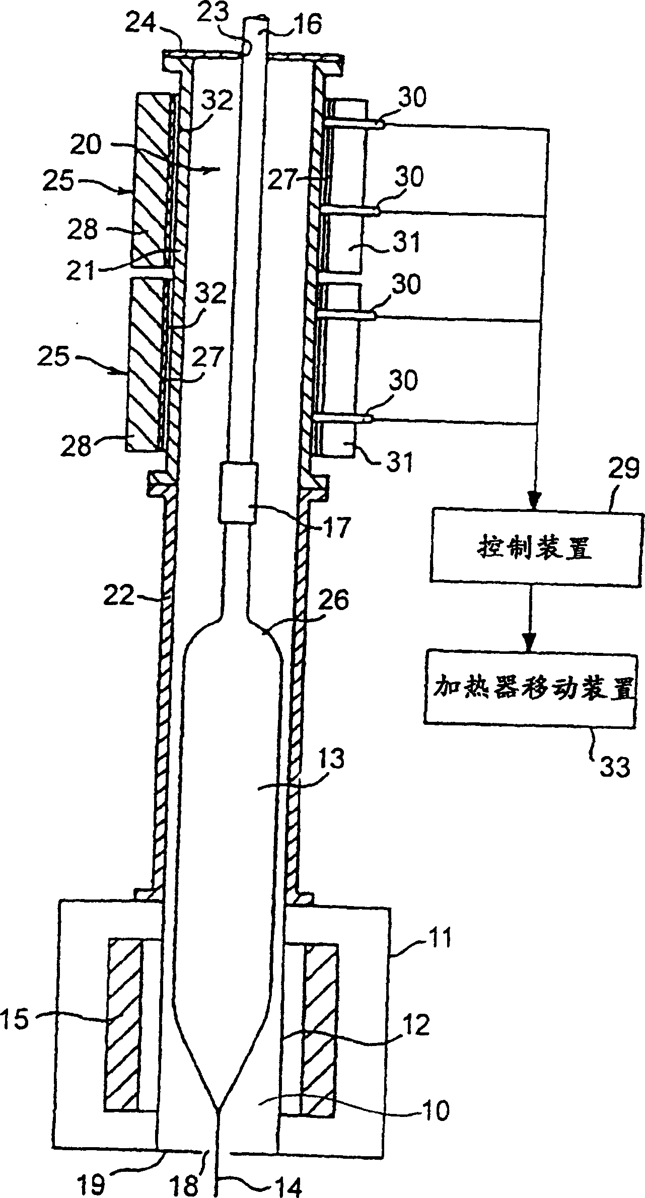
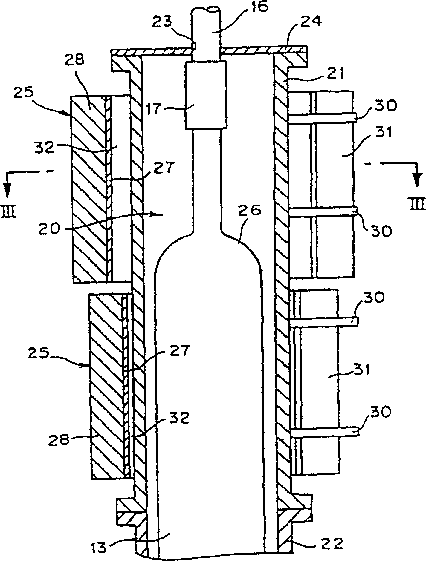
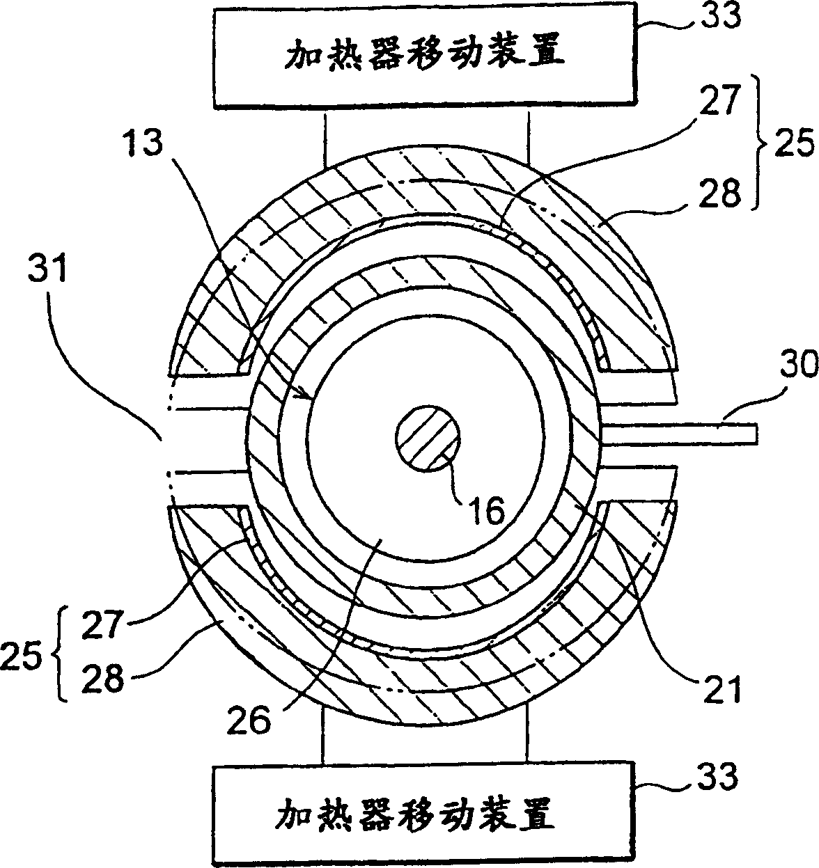
[0024] figure 1 It is a sectional view showing the structure of the first embodiment of the optical fiber drawing furnace of the present invention, figure 2 is an enlarged view showing its main part, image 3 yes figure 2 Sectional view of III-III in.

[0025] The fiber drawing furnace is equipped with a furnace body 11 made of stainless steel and lined with heat insulating material. A cylindrical furnace core tube 12 is arranged at the central portion of the furnace body 11 , and an annular graphite heater 15 is arranged around it, that is, between the furnace body 11 . The furnace tube 12 and the graphite heater 15 are arranged co...


PUM


Abstract

A fiber drawing method according to the present invention is a drawing method of optical fiber for drawing an optical fiber 14 from one end of a fiber preform 13 by softening with heat, wherein the fiber preform 13 is set in a semi-closed space 10, 20 opening in part at a lower end in a fiber drawing furnace, the fiber preform 13 is heated by a heater 15 disposed on the lower end side of this semi-closed space 10, 20, and fiber drawing is carried out with adjusting a quantity of heat dissipation from the upper portion 20 of this semi-closed space.

Description

[0001] This application is a divisional application of the application dated October 29, 1999, the application number is 99810340.3, and the invention name is an optical fiber drawing method and a drawing furnace. technical field [0002] The invention relates to an optical fiber drawing method for suppressing linear fluctuations and an optical fiber drawing furnace adopting the method. Background technique [0003] Usually, an optical fiber is manufactured by heating a rod-shaped optical fiber base material in an optical fiber drawing furnace to soften it and draw it. Furthermore, making the size of the base material long and reducing the frequency of its replacement are effective in reducing the manufacturing cost of the optical fiber. Now, one drawing can make an optical fiber with a length of hundreds of kilometers. [0004] In order to stably draw such a long optical fiber base material, the drawing furnace has also been improved. A drawing furnace disclosed in Japane...

Claims


Application Information

Patent Timeline
Patent Type & Authority Applications(China)
IPC IPC(8): C03B37/025C03B37/027C03B37/029G02B6/00
CPCC03B2205/72C03B2205/63C03B37/029C03B37/0253C03B37/02736C03B2205/80C03B2205/70
Inventor 樽稔树土屋一郎常石克之永山胜也桑原一也
Owner SUMITOMO ELECTRIC IND LTD
Why Eureka
Try Eureka