
Light source module

A technology of light source module and light source group, applied in the direction of light source, electric light source, optics, etc.

Inactive Publication Date: 2005-01-05
AU OPTRONICS CORP
View PDF0 Cites 5 Cited by
  • Summary
  • Abstract
  • Description
  • Claims
  • Application Information

AI Technical Summary

Problems solved by technology

[0005] In view of this, the purpose of the present invention is to provide a light source module, which is designed to cover the light emitting diodes with a light guide cover, which can guide the light of the light emitting diodes to be emitted to the outside through the light guide port of the light guide cover, solving the problem of traditional The problem of invalid light-emitting area produced by the light source module, and greatly improve the brightness quality of the light source module

Method used


Image

  • Light source module
  • Light source module
  • Light source module

Examples


Embodiment 1

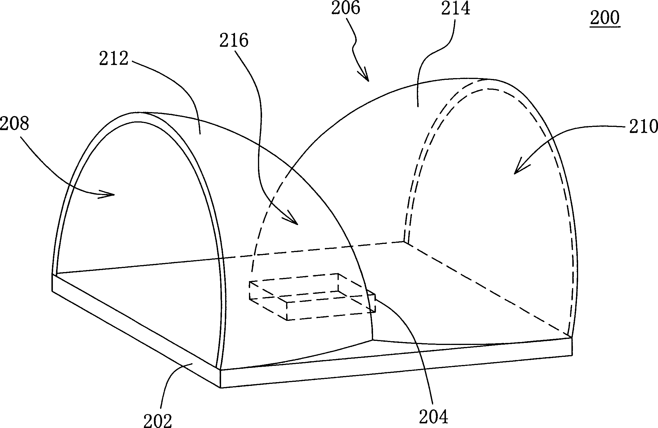
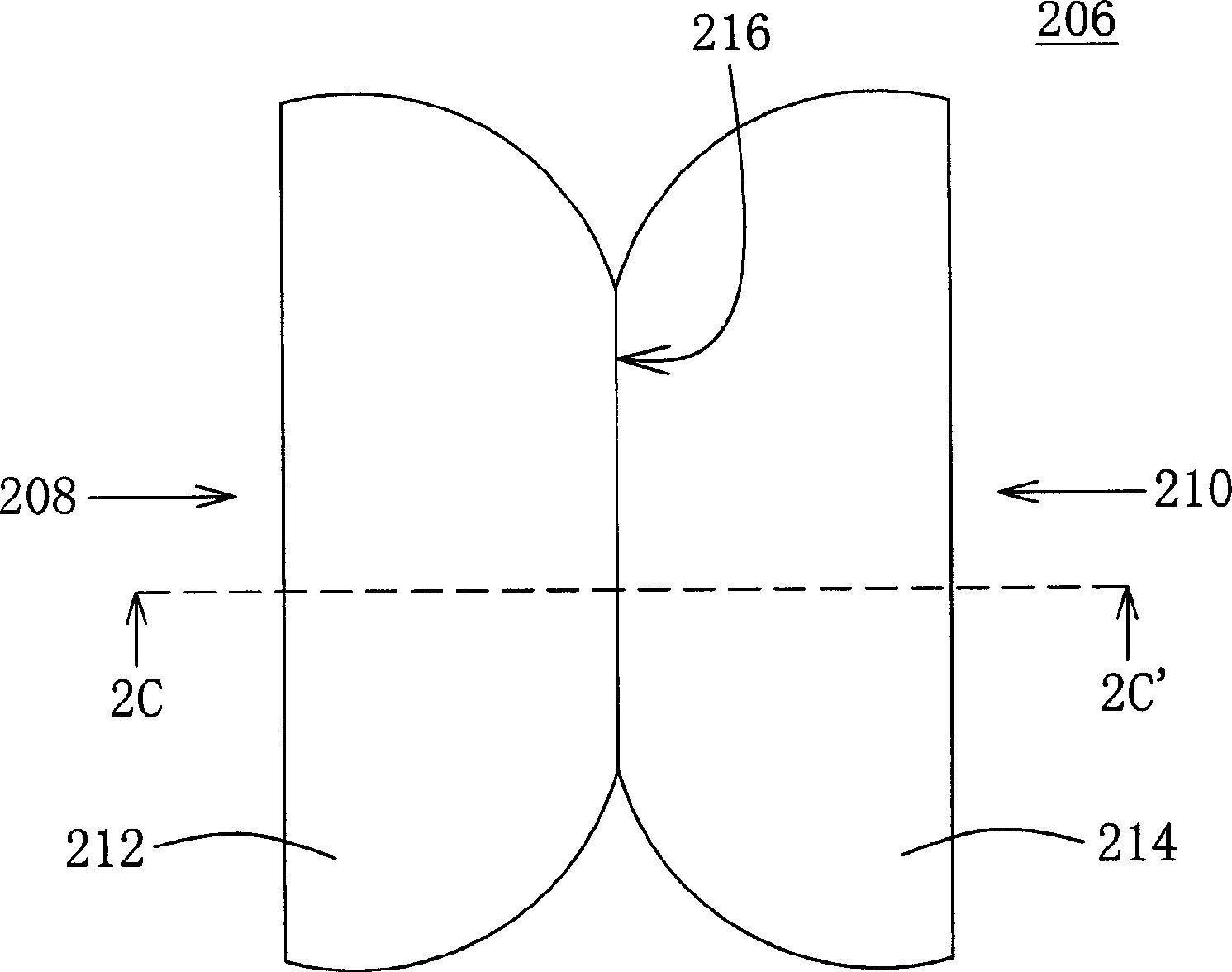
[0015] Please also refer to Figure 2A-2C , Figure 2A A schematic perspective view of a light source module according to a first embodiment of the present invention is shown, Figure 2B Shown is Figure 2A The top view of the light source module, Figure 2C is shown along the Figure 2B The cross-sectional view of the light source module viewed by the section line 2C-2C'.

[0016] exist Figure 2A-2C Among them, the light source module 200 includes a circuit board 202 , a light emitting diode 204 and a light guide cover (shell) 206 . The LED 204 is disposed on the circuit board 202 for providing light. The light guide cover 206 is disposed on the circuit board 202 to cover the LED 204 , and the light guide cover 206 has a first light export port 208 and a second light export port 210 opposite to each other.

[0017] If further subdivided, the light guide cover 206 includes a first arc-shaped light guide cover 212 and a second arc-shaped light guide cover 214 . One end...

Embodiment 2

[0022] Please refer to image 3 , which is a top view of the light source module according to the second embodiment of the present invention. The light source module 400 includes a circuit board 402 , a row of light source groups 404 , light guide plates 406 and 408 , and several light guide covers 206 as described in the first embodiment. The row of light source groups 404 has several light emitting diodes 204 described in the first embodiment, and is arranged on the circuit board 402 . The light guide plates 404 and 406 are disposed outside the two sides of the row of light source groups 404 .

[0023] Because the light emitting diodes 204 are arranged in a straight line, two adjacent light emitting diodes 204 will form an invalid light emitting area between each other. In order to eliminate the existence of the invalid light emitting area, each light emitting diode 204 is covered with a corresponding light guide cover 206 respectively. In other words, each light guide co...


PUM


Abstract

A light source module includes a CB, a light emitting diode and a light conduction shell which is matched on the CB in the way of covering the diode and has related first and a second light conduction ports at both sides of the diode and leads the light of the diode to emit to outside forming two-way conduction lights through the two ports.

Description

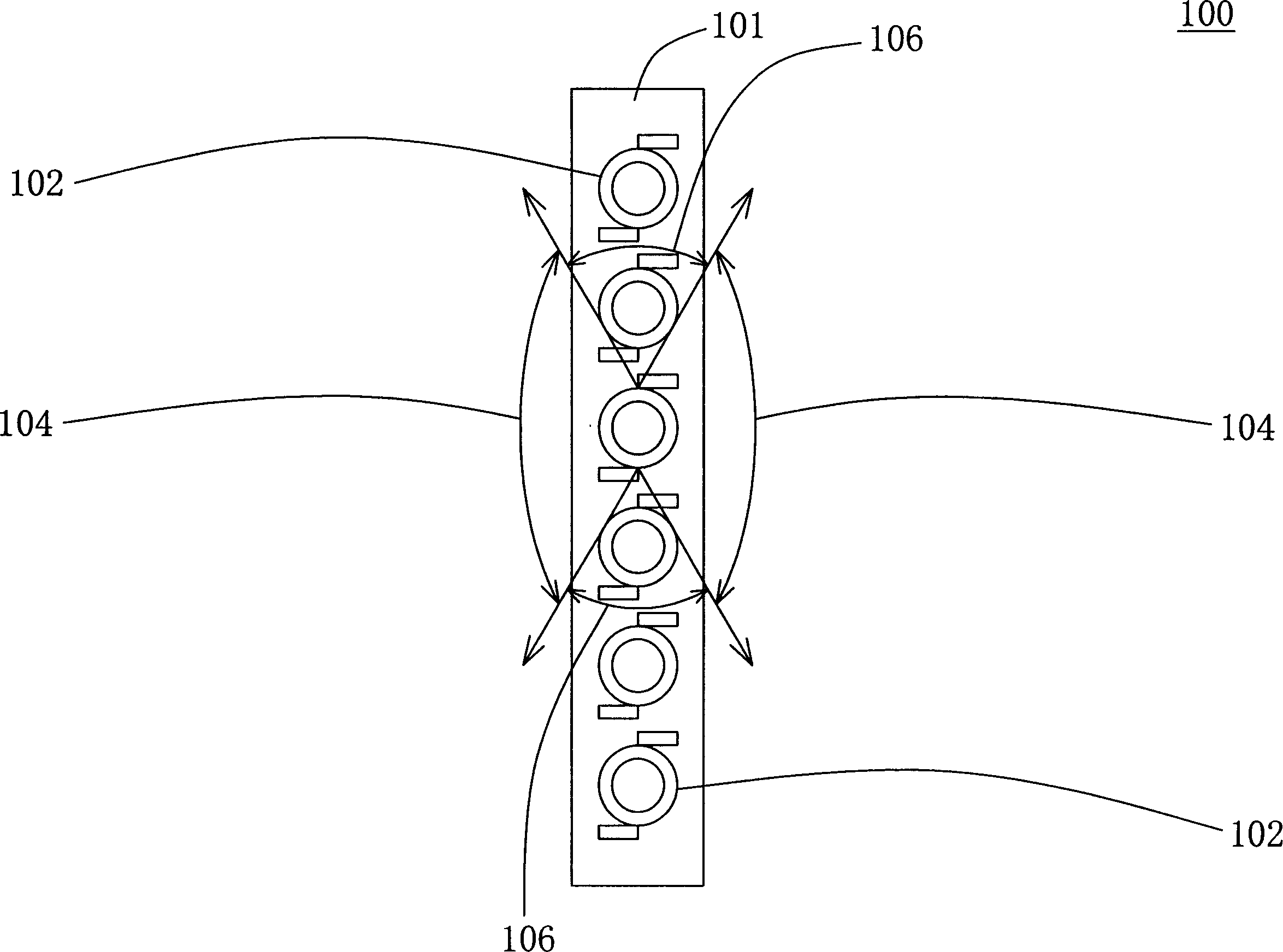
【Technical field】 [0001] The present invention relates to a light source module, and in particular to a light source module capable of guiding light in two directions. 【Background technique】 [0002] Light Emitting Diode (LED) has many advantages, such as fast response speed, long luminous life, small size, low power consumption, low heat generation and high reliability, so it has gradually become the main light emitting diode of backlight modules. components. Among them, many light emitting diodes can be arranged into an array light source module. [0003] Please refer to figure 1 , which is a partial top view of a conventional light source module. exist figure 1 Among them, the light source module 100 at least includes a circuit board 101 and several light emitting diodes 102 . These light emitting diodes 102 are arranged along a straight line, like a row of light source groups, and are arranged on the circuit board 101 . Since the light provided by each LED 102 is s...

Claims


Application Information

Patent Timeline
IPC IPC(8): F21K9/61F21V8/00F21Y115/10H01L33/00
Inventor 周信宏周晖凯
Owner AU OPTRONICS CORP
Learn More