Method and device for attenuating the motion of hydraulic cylinders of mobile work machinery

A technology of engineering machinery and hydraulic cylinders, applied in the field of hydraulic cylinder movement, can solve problems such as inflow side not being fully filled, braking too late, hydraulic cylinder braking, etc.

Inactive Publication Date: 2005-01-19
LIEBHERR FRANCE
View PDF0 Cites 16 Cited by
  • Summary
  • Abstract
  • Description
  • Claims
  • Application Information

AI Technical Summary

Problems solved by technology

Depending on the switching speed of the directional control valve, which causes the movement to be decelerated
[0007] However, applying this approach, braking is usually either too early or too late
This means that either the momentum has not been fully utilized, or the hydraulic cylinder is still reaching the mechanical limit braking at excessive speed
Also, during uncontrolled de-energization, pressure peaks occur on the outflow side while the inflow side is not fully filled, both of which lead to increased loads on the various working systems and hydraulic components

Method used


Image

  • Method and device for attenuating the motion of hydraulic cylinders of mobile work machinery
  • Method and device for attenuating the motion of hydraulic cylinders of mobile work machinery
  • Method and device for attenuating the motion of hydraulic cylinders of mobile work machinery

Examples


Embodiment Construction

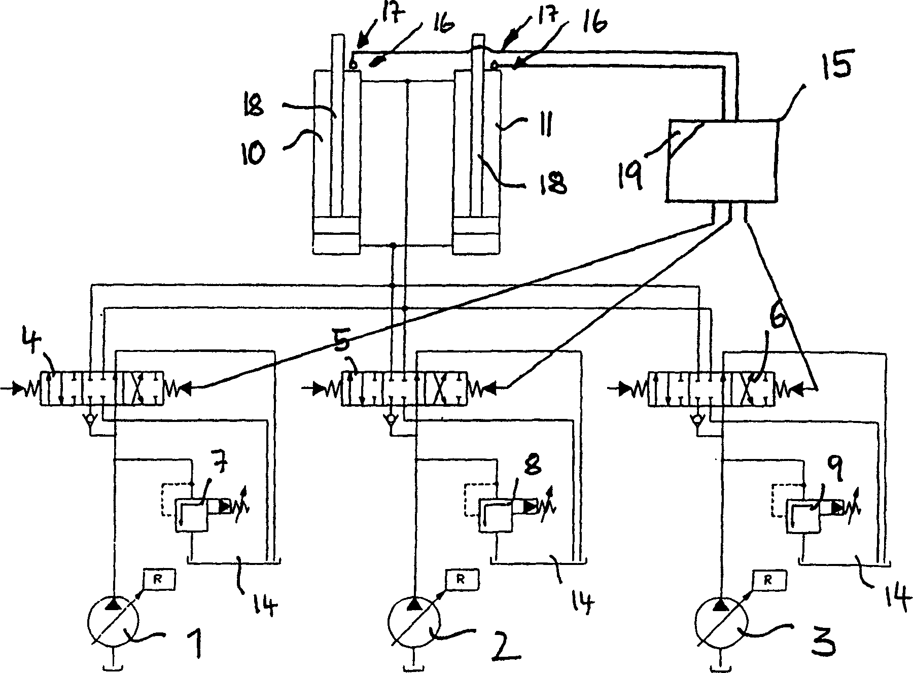
[0029] Such as figure 1 As shown, hydraulic cylinders 10 and 11 , which may be lift cylinders of a hydraulic excavator, for example, are driven by a hydraulic drive comprising three hydraulic pumps 1 , 2 and 3 , each of which can be adjusted via a regulator R. Three hydraulic pumps 1, 2 and 3 are each connected via directional control valves 4, 5 and 6 respectively to hydraulic cylinders 10 and 11, said hydraulic cylinders 10 and 11 being switched in parallel relation to each other. Via the directional control valves 4, 5 and 6, the inflows and outflows to and from the respective pumps 1, 2 and 3 of the hydraulic cylinders 10 and 11 can be cut off and closed in a manner known per se, or can be established to the pumps. A flow connection in which the direction of flow is reversible allowing the cylinder to extend and contract. Upstream of the directional control valves 4 , 5 and 6 , the pressure lines from the pumps 1 , 2 and 3 include relief valves 7 , 8 and 9 through which ...


PUM


Abstract

To solve disadvantages of a method and a device for damping the movement of a cylinder, in particular, a hydraulic cylinder of a mobile working machine such as a hydraulic drilling machine. Before piston rods of hydraulic cylinders reach the limit of each moving stroke, the moving speed is recorded, and the time points to start the adjustment are changed according to the recorded moving speed. A movement damping device comprises a position recorder to record the preliminary limit position of the piston rods of the hydraulic cylinders, flow rate controllers to adjust the flow-in and / or flow-out of the pressurized liquid with respect to the hydraulic cylinders, and a control device to control the flow rate controllers when the piston rods reach the preliminary limit position. The moving speed is recorded when the piston rods reach the preliminary limit position, and the drive of the flow rate controllers is delayed according to the recorded moving speed.

Description

technical field [0001] The present invention relates to a method and a device for attenuating the movement of a hydraulic cylinder of a movable engineering method and machine, in particular a hydraulic excavator, wherein the arrival of the hydraulic cylinder to an initial limit position is recorded by a position recording device; before, decelerating its movement speed; and only at the reduced speed to move the hydraulic cylinder to the limit of each stroke. For this purpose, a flow control device is provided for throttling the inflow and / or outflow of the hydraulic cylinder, and when the initial limit position is reached, the throttle is correspondingly driven by the control device in order to throttle the inflow or outflow of the hydraulic cylinder traffic. Background technique [0002] The attenuation of the hydraulic cylinder movement or the de-energization of the travel limit ensures that the speed of the hydraulic cylinder is reduced just before the mechanical limit b...

Claims


Application Information

Patent Timeline
Patent Type & Authority Applications(China)
IPC IPC(8): F15B15/22E02F9/22F15B11/04F15B11/048F15B21/02
CPCF15B2211/30525F15B2211/7053F15B2211/755F15B2211/6336F15B2211/715F15B2211/327F15B2211/7128E02F9/2214F15B2211/20576F15B2211/20546F15B2211/31588F15B2211/665F15B11/048F15B21/02
Inventor F·赫尔布林G·科斯曼
Owner LIEBHERR FRANCE
Why Eureka
Try Eureka