Adapter for braking deceleration device

A deceleration device and adapter technology, which is applied in the direction of switches with braking devices, multi-purpose hand tools, manufacturing tools, etc., can solve the problem of high damper installation cost

Inactive Publication Date: 2005-01-26
ARTURO SALICE
View PDF1 Cites 10 Cited by
  • Summary
  • Abstract
  • Description
  • Claims
  • Application Information

AI Technical Summary

Problems solved by technology

The installation cost of such a combined damper is high

Method used


Image

  • Adapter for braking deceleration device
  • Adapter for braking deceleration device
  • Adapter for braking deceleration device

Examples


Embodiment Construction

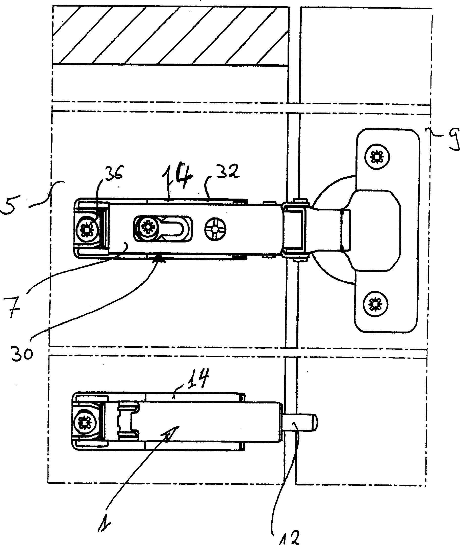
[0018] figure 1 A top view is shown of the side walls of the furniture frame 5 in the open position and of the door 9 , which has been secured by hinges 7 in the usual manner.

[0019] The brake retarder 1 according to the invention is also connected to the side wall of the furniture part, on which brake retarder 1 the hinge 7 is arranged. Because of the short distance from the hinge axis of the door 9, the damper 12 used in the brake retarder 1 may comprise a damping liquid with a viscosity of at least 15000 cSt.

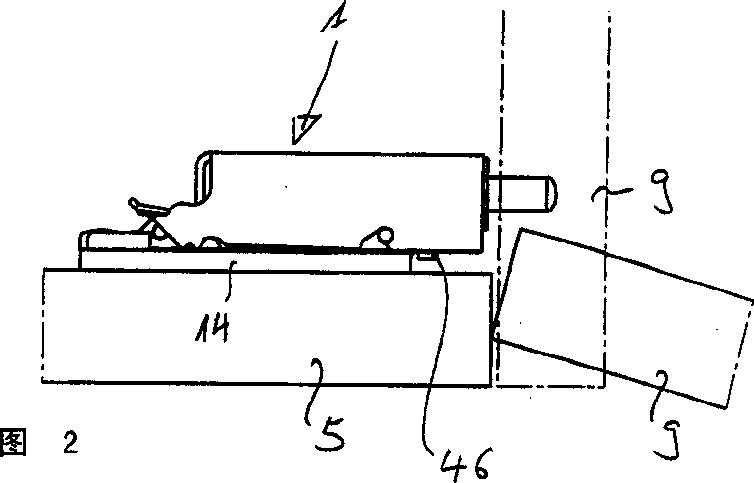
[0020] FIG. 2 shows a side view of the brake reduction gear 1 . The open position of the door 9 is shown by solid lines and its closed position by dashed lines.

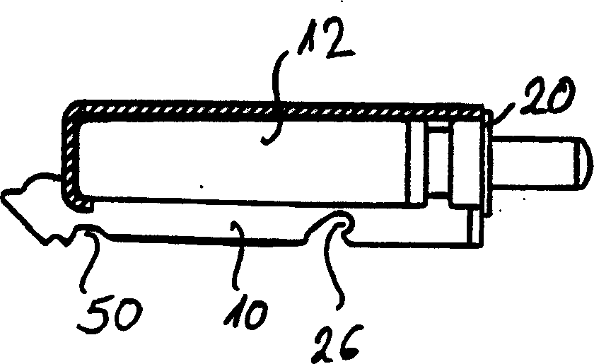
[0021] image 3 A longitudinal cross-sectional view of the adapter 10 with the damper 12 integrated is shown. The longitudinal sectional view according to FIG. 5 shows the front tab 16 in the adapter body 10 and the rear web 18 arranged at an angle, wherein the adapter 12 (with image 3 In contrast) ...


PUM


Abstract

The invention relates to an adaptor for a braking deceleration device for doors or movable furniture parts, which essentially comprises a plunger which can be pushed into a housing against a braking force, with an adaptor body. According to the invention, the adaptor body comprises at least one accommodation recess for accommodating the housing of the braking deceleration device, and the adaptor body comprises suitable means by way of which it can be fixed to an attachment plate and via it to the frame or furniture carcass.

Description

technical field [0001] The invention relates to an adapter for a brake retarder of a door or movable furniture part, the brake retarder essentially comprising a plunger which can be pressed into a housing against an actuation force, said adapter having an adapter body. Background technique [0002] From European Patent Application No. BP1006251A1 a brake retarder is known which comprises a plunger which can be pressed into a housing or cylinder against a braking or damping force. Said housing or cylinder is connected to the face of a frame or furniture frame by means of connecting means, wherein said connecting means have a specific arrangement, ie they require special care to be used during the installation of the brake retarder. From BP10159140A it is known to design at least one hinge as a purely damped hinge without closure means, wherein the damper is arranged in or on the hinge arm and / or in or on the hinge pot. The hinge arm, fixable to the side wall of the furniture...

Claims


Application Information

Patent Timeline
Patent Type & Authority Applications(China)
IPC IPC(8): E05F5/10E05D7/04E05D7/12E05F5/00E05F5/02
CPCE05F5/006E05Y2800/205E05Y2201/21E05Y2600/46Y10T16/2771E05Y2900/20E05D7/125E05Y2201/256E05Y2201/264E05Y2600/45E05F5/02Y10T16/62E05F5/10
Inventor 发明人要求不公开姓名
Owner ARTURO SALICE
Why Eureka
Try Eureka