
Oil cylinder

A technology for oil cylinders and cylinder blocks, which is applied in the field of oil cylinders that can control the stroke, and can solve the problems of piston rod damage, unfavorable oil sealing, etc., and achieve the effects of preventing impact, simple structure, and compact volume

Active Publication Date: 2020-07-14
扬州苏油油成商贸实业有限公司
View PDF3 Cites 1 Cited by
  • Summary
  • Abstract
  • Description
  • Claims
  • Application Information

AI Technical Summary

Problems solved by technology

In the prior art, there are some oil cylinders that can adjust the stroke, but most of them need to fix the positioner and clamp on the piston rod, which will cause certain damage to the piston rod, which is not conducive to oil sealing; and this solution can only control the extension of the oil cylinder Longest retracted stroke, limited use

Method used


Image

  • Oil cylinder
  • Oil cylinder
  • Oil cylinder

Examples


Embodiment Construction

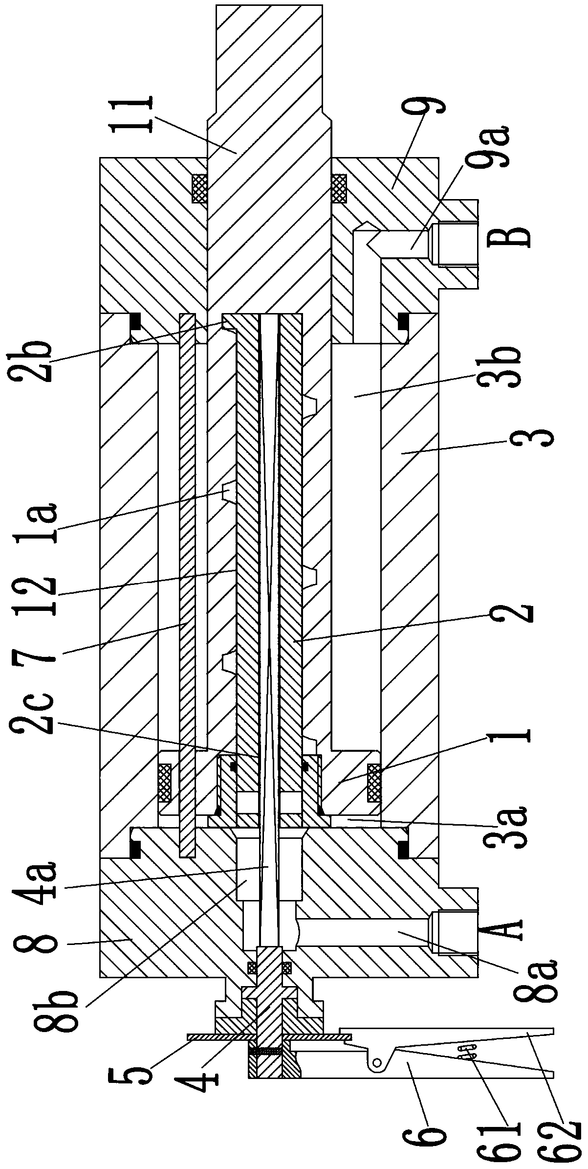
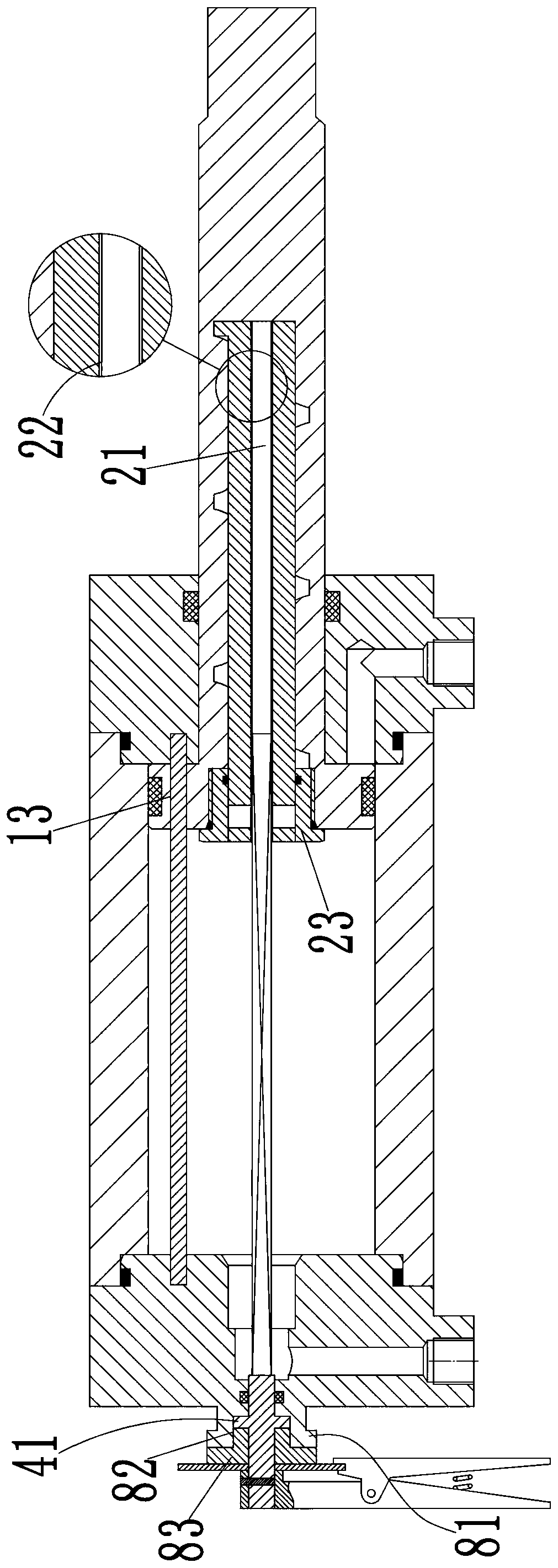
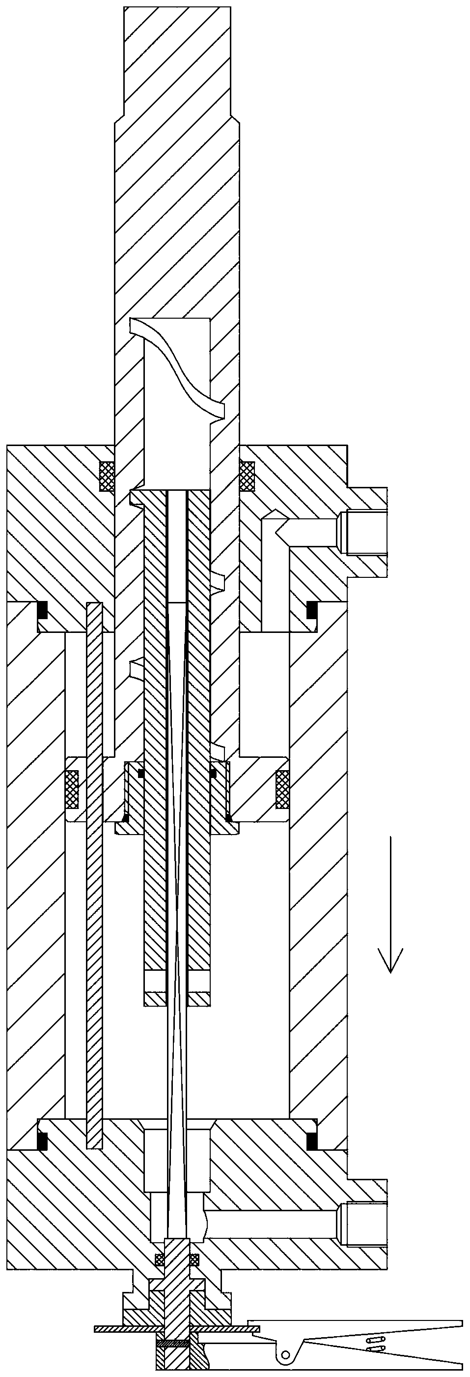
[0020] see Figure 1-4 As shown, an oil cylinder comprises a cylinder body 3, a left end cover 8 is fixedly installed on the left end of the cylinder body 3, a right end cover 9 is fixedly installed on the right end, a piston body 1 is slidably connected in the cylinder body 3, and the piston body 1 The right end of the body 1 is provided with a piston rod 11 protruding from the right end cover 9, a rodless cavity 3a is formed between the piston body 1 and the left end cover 8 in the cylinder body 3, and a rod is formed between the piston body 1 and the right end cover 9. Cavity 3b; the side of the right end cover 9 is provided with a B port, the left end cover 8 is provided with a valve hole 8b on the side facing the piston body 1, and the side of the left end cover 8 is provided with an A port; the left end cover 8 There is a first through hole 8a for connecting port A and valve hole 8b, and the right end cover 9 is provided with a second through hole 9a for connecting port ...


PUM


Abstract

The invention discloses an oil cylinder. The oil cylinder comprises a cylinder body, wherein a left end cover is fixedly installed at the left end of the cylinder body, a right end cover is fixedly installed at the right end of the cylinder body, a piston body is slidably connected into the cylinder body, a piston rod extending out of the right end cover is installed at the right end of the pistonbody, a rodless cavity is formed between the piston body and the left end cover in the cylinder body, and a rod cavity is formed between the piston body and the right end cover; an opening B communicating with the rod cavity is formed in the side surface of the right end cover, a valve hole is formed in the side surface, facing the piston body, of the left end cover, and an opening A communicating with the valve hole is formed in the side surface of the left end cover; mounting holes are formed in the piston body and the piston rod in the axial direction of the piston rod, sleeve rods are installed in the mounting holes, an adjusting assembly is installed in the left end cover, and the adjusting assembly is used for controlling the length of the portions, extending out of the mounting holes, of the left ends of the sleeve rods. The oil cylinder is simple in structure, and can achieve the adjustment of the stroke of the oil cylinder.

Description

technical field [0001] The invention belongs to the technical field of oil cylinders, and in particular relates to an oil cylinder capable of controlling stroke. Background technique [0002] The hydraulic cylinder is a hydraulic actuator that performs linear reciprocating motion (or swing motion). It is widely used in various mechanical hydraulic systems. Hydraulic cylinders are divided into piston type, plunger type, swing type and telescopic type according to the structure type, among which the piston type hydraulic cylinder is the most widely used. Piston hydraulic cylinders are usually composed of cylinder block, cylinder piston, piston rod, front and rear cylinder heads, etc. The transmission distance is the stroke of the piston rod. However, in actual use, sometimes the transmission distance of the cylinder needs to be variable. In the prior art, there are some oil cylinders that can adjust the stroke, but most of them need to fix the positioner and clamp on the pi...

Claims


Application Information

Patent Timeline
Patent Type & Authority Applications(China)
IPC IPC(8): F15B15/14F15B15/20
CPCF15B15/1438F15B15/1428F15B15/20F15B2211/765
Inventor 邵玉强其他发明人请求不公开姓名
Owner 扬州苏油油成商贸实业有限公司
Learn More