Pressure self-adjustment crankcase ventilation valve with composite filter structure

A composite filtering and self-adjusting technology, applied in crankcase ventilation, engine components, machines/engines, etc., can solve the problems of high crankcase pressure, high crankcase pressure, complex structure, etc., and achieve automatic adjustment of crankcase pressure, high Efficient oil and gas separation, compact structure and reasonable effect

Inactive Publication Date: 2019-05-10
JIANGXI ISUZU ENGINE CO LTD
View PDF5 Cites 1 Cited by
  • Summary
  • Abstract
  • Description
  • Claims
  • Application Information

AI Technical Summary

Problems solved by technology

The existing engine crankcase breather valve can realize a closed cycle, but it cannot effectively reduce the pollution of the oil-air mixture caused by crankcase blow-by
[0004] In the prior art, there are mainly the following two types of crankcase ventilation valves: 1) collision structure, including baffle type, labyrinth type, spiral type, etc., with simple structure and low cost, but the separation efficiency is not high; 2) Active structures, including electric acceleration and capture, are complex in structure and high in cost, but have high separation efficiency
[0005] In addition, the blow-by gas in the crankcase of the engine will accumulate to a certain extent to cause the crankcase pressure to be too high, and the amount of blow-by gas in the crankcase of the engine changes with the engine speed. The amount of blow-by gas in the crankcase will also have a sudden change, resulting in excessive pressure in the crankcase of the engine, resulting in oil seal leakage and other failures. The existing engine crankcase breather valve cannot adapt to changes in crankcase pressure.

Method used


Image

  • Pressure self-adjustment crankcase ventilation valve with composite filter structure
  • Pressure self-adjustment crankcase ventilation valve with composite filter structure
  • Pressure self-adjustment crankcase ventilation valve with composite filter structure

Examples


Embodiment Construction

[0028] The following will clearly and completely describe the technical solutions in the embodiments of the present invention with reference to the drawings in the embodiments of the present invention.

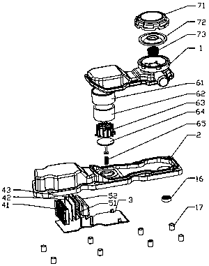
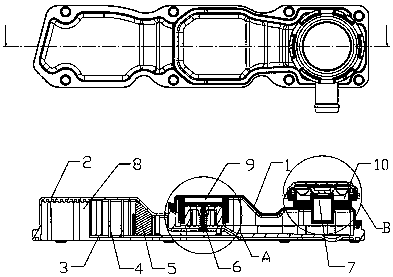
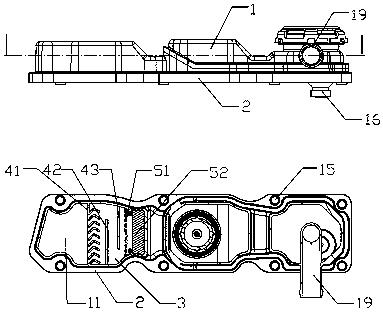
[0029] Such as Figures 1 to 7 The pressure self-adjusting crankcase breather valve of the composite filter structure of the present invention shown includes an upper cover plate 1, a middle cover plate 2, a bottom plate 3, an initial filter assembly 4, a fine filter assembly 5, and an ultrafine filter assembly 6 And the diaphragm valve assembly 7, the upper cover plate 1 and the bottom plate 3 are respectively welded to the upper and lower end faces of the middle cover plate 2, and form three cavities in sequence from left to right: the first cavity 8, the second cavity 9 and the third cavity Cavity 10, the bottom of the first cavity 8 and the second cavity 9 are connected, the primary filter assembly 4 and the fine filter assembly 5 are placed in the first cavity 8, and the ...


PUM


Abstract

The invention discloses a pressure self-adjustment crankcase ventilation valve with a composite filter structure. The pressure self-adjustment crankcase ventilation valve with the composite filter structure comprises an upper cover plate, a middle cover plate, a base plate, a primary filter module, a fine filter module, an ultrafine filter module and a diaphragm valve module; the upper cover plateand the base plate are fixedly connected to the upper and lower end surfaces of the middle cover plate to form three cavities in sequence from left to right: a first cavity, a second cavity and a third cavity; the first cavity communicates with the bottom of the second cavity; the primary filter module and the fine filter module are positioned in the first cavity; the ultrafine filter module is positioned in the second cavity; and the diaphragm valve module is positioned in the third cavity. The composite filter structure with primary filtration, fine filtration and ultrafine filtration is provided; meanwhile, the automatic adjustment of the pressure of a crankcase can be realized through an adjusting rod and an adjusting spring; oil and gas can be separated with higher efficiency; meanwhile, the pressure self-adjustment effect is achieved; and the whole structure is compact and reasonable.

Description

technical field [0001] The invention belongs to the technical field of engines, and in particular relates to a pressure self-adjusting crankcase breather valve with a compound filter structure. Background technique [0002] The compression stroke of the engine compresses the air and fuel in the combustion chamber through the movement of the piston, and then converts chemical energy into kinetic energy through ignition or compression ignition. However, when the piston performs compression work, due to the gap between the piston and the piston ring, the piston ring and the cylinder barrel, blow-by gas is discharged in the crankcase of the engine. Therefore, in order to solve the crankcase gas blow-by problem of engine, a crankcase ventilation device is arranged in design, generally all design crankcase ventilation valve in the prior art. [0003] With the improvement of emission regulations, the engine is required to implement a forced ventilation cycle, that is, a closed cyc...

Claims


Application Information

Patent Timeline
Patent Type & Authority Applications(China)
IPC IPC(8): F01M13/00F01M13/04
Inventor 殷志雄黄越杏杨闯袁经煌黄辰君王彤
Owner JIANGXI ISUZU ENGINE CO LTD
Why Eureka
Try Eureka