
Circuit arrangement and method for an illumination device having settable color and brightness

A technology of lighting device and circuit structure, which is applied in the direction of lighting device, electric lamp circuit layout, electric light source, etc., and can solve the problems that the color and brightness cannot be adjusted comfortably, and a large number of

Inactive Publication Date: 2005-01-26
PATENT TREUHAND GESELLSCHAFT FUR ELECTRIC GLUEHLAMPEN MBH
View PDF0 Cites 7 Cited by
  • Summary
  • Abstract
  • Description
  • Claims
  • Application Information

AI Technical Summary

Problems solved by technology

[0006] In the prior art, it has been shown that the disadvantage is that the provision of the above-mentioned light colors requires a great deal of expense and that the color and brightness cannot be comfortably adjusted without additional expense

Method used


Image

  • Circuit arrangement and method for an illumination device having settable color and brightness
  • Circuit arrangement and method for an illumination device having settable color and brightness
  • Circuit arrangement and method for an illumination device having settable color and brightness

Examples


Embodiment Construction

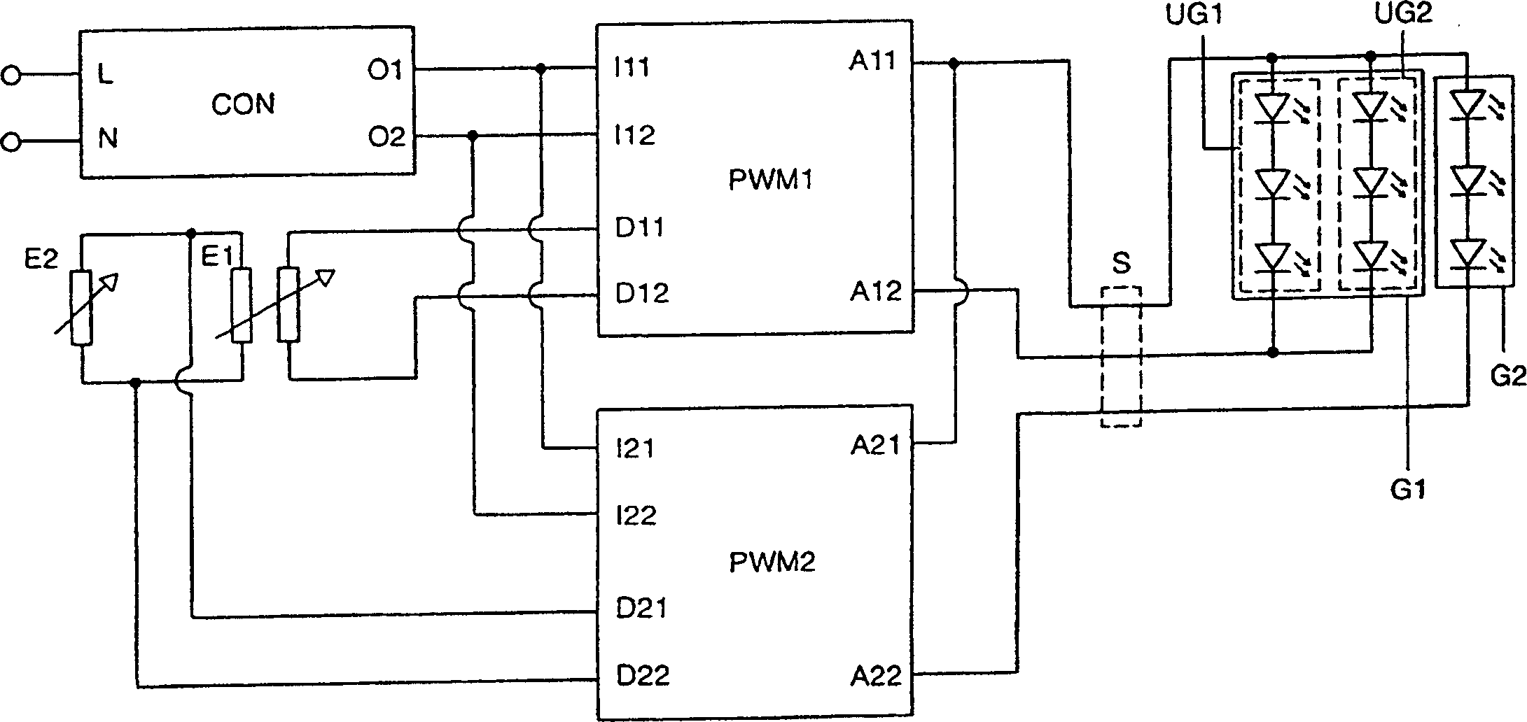
[0026] figure 2 A block diagram of a preferred embodiment of the invention is shown in . The block diagram shows a preferred embodiment of a circuit configuration with connected light sources.

[0027] The voltage converter CON draws its electrical energy via connections L and N from a power source (not shown), realized for example by a mains supply or a battery. The voltage converter CON supplies at its terminals O1 and O2 an operating voltage which is suitable for operating a light source connected to the circuit arrangement.

[0028] The operating voltage is fed into the first and second dimming devices (PWM1, PWM2) via the connection terminals I11 and I12 and I21 and I22. The first dimming device PWM1 has two connection terminals A11 and A12 to which the light sources of the first group G1 are connected. The second dimming device PWM2 has two connections A21 and A22, to which light sources of the second group G2 are connected.

[0029] In the exemplary embodiment show...


PUM


Abstract

It is intended to be possible to use a respective setting apparatus (E1, E2) to set the color and the brightness of an illumination device separately. Light sources having three different colors are operated for this purpose. Only one first power supply (CON, PWM1) is provided for two colors, whereas the third color is supplied by a second power supply (CON, PWM2). The brightness can be set by altering the power output of the first (CON, PWM1) and the second (CON, PWM2) power supplies at the same time. The color can be set by altering the power output of the second (CON, PWM2) power supply.

Description

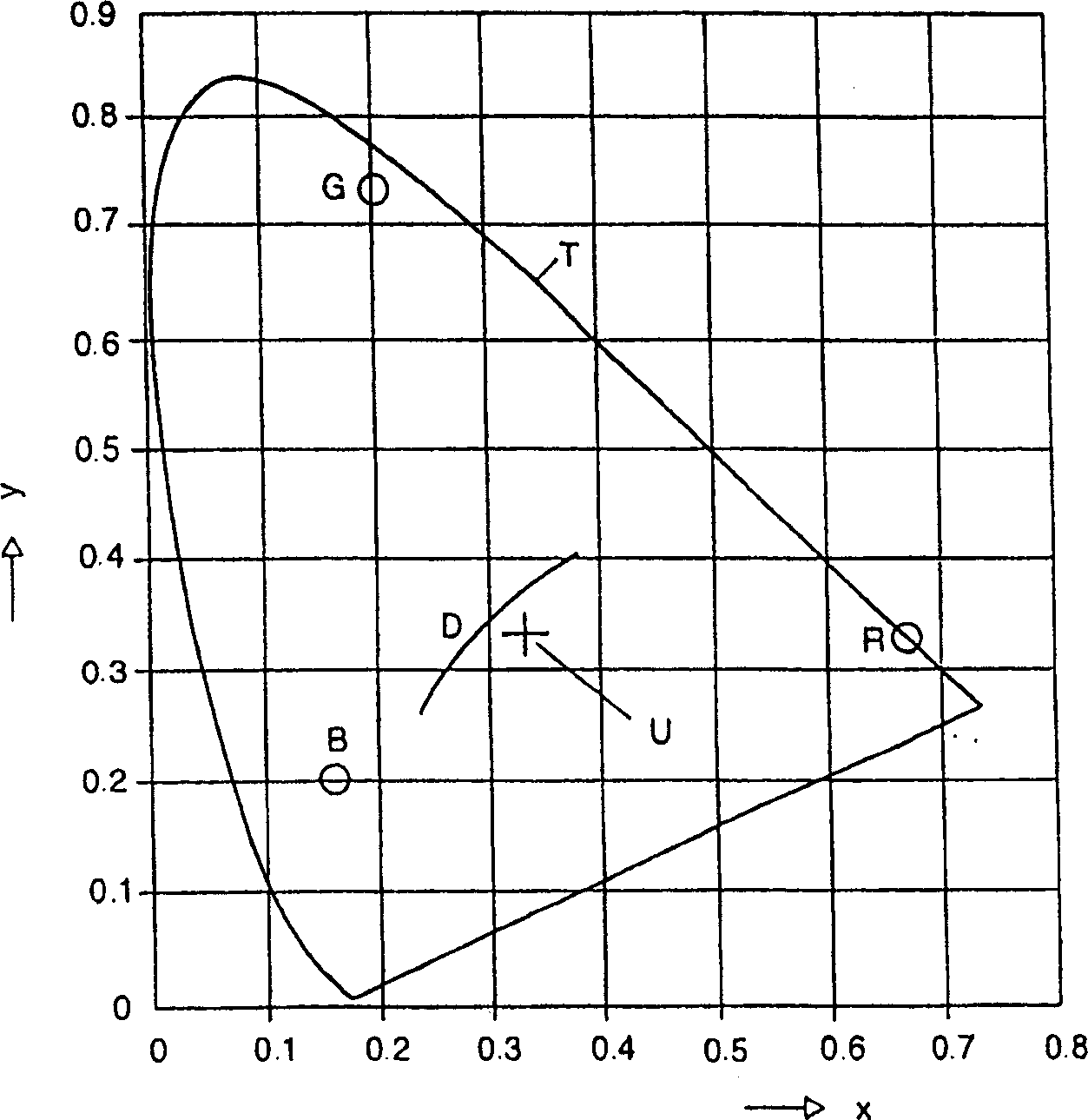
technical field [0001] The invention relates to a circuit structure for an illuminating device. In particular, this relates to a circuit arrangement which makes it possible to adjust both the color and the brightness of the emitted light in a lighting device. Background technique [0002] The color of the light source, also known as chromaticity in the literature, is generally determined by a standard color chart. Such a color chart is defined in the German Industrial Standard DIN5033 or the equivalent international standard CIE1931. Colors are determined by x-coordinates and y-coordinates in a color chart. exist figure 1 A standard color chart is shown in . All human-visible colors are in the color triangle T. The so-called achromatic point U is defined with the coordinates x=0.33 and y=0.33. The color in the area around the achromatic point U is generally perceived as white. The color taken by sunlight during the day is on the so-called D line D. [0003] In order ...

Claims


Application Information

Patent Timeline
Patent Type & Authority Applications(China)
IPC IPC(8): H05B37/00H05B37/02H05B44/00
CPCH05B33/0818Y02B20/346H05B33/0863H05B33/0866H05B37/02H05B45/24H05B45/20H05B45/37A01K97/04A01K97/06Y02B20/30
Inventor M·布罗埃德尼内A·法勒
Owner PATENT TREUHAND GESELLSCHAFT FUR ELECTRIC GLUEHLAMPEN MBH
Learn More