Check patentability & draft patents in minutes with Patsnap Eureka AI!

Rear floor part structure for vehicle

A technology of component structure and rear floor, which is applied to vehicle components, superstructure, and superstructure sub-assemblies, etc., can solve problems such as fuel leakage and injuries to rear seat passengers.

Inactive Publication Date: 2005-02-02
HYUNDAI MOTOR CO LTD
View PDF1 Cites 13 Cited by
  • Summary
  • Abstract
  • Description
  • Claims
  • Application Information

AI Technical Summary

Problems solved by technology

[0004] In a rear-end collision, the force of the impact is likely to propel the body of the car toward the front, causing fuel to leak from the damaged fuel tank and injuring rear-seat passengers

Method used


Image

  • Rear floor part structure for vehicle
  • Rear floor part structure for vehicle
  • Rear floor part structure for vehicle

Examples


Embodiment Construction

[0014] Preferred embodiments of the present invention will be described in detail below with reference to the accompanying drawings.

[0015] Embodiments of the present invention serve to increase the rigidity of the rear floor member constituting the cargo space, thereby maximizing the amount of propulsion of the rear floor member toward the front of the vehicle in the event of a rear collision.

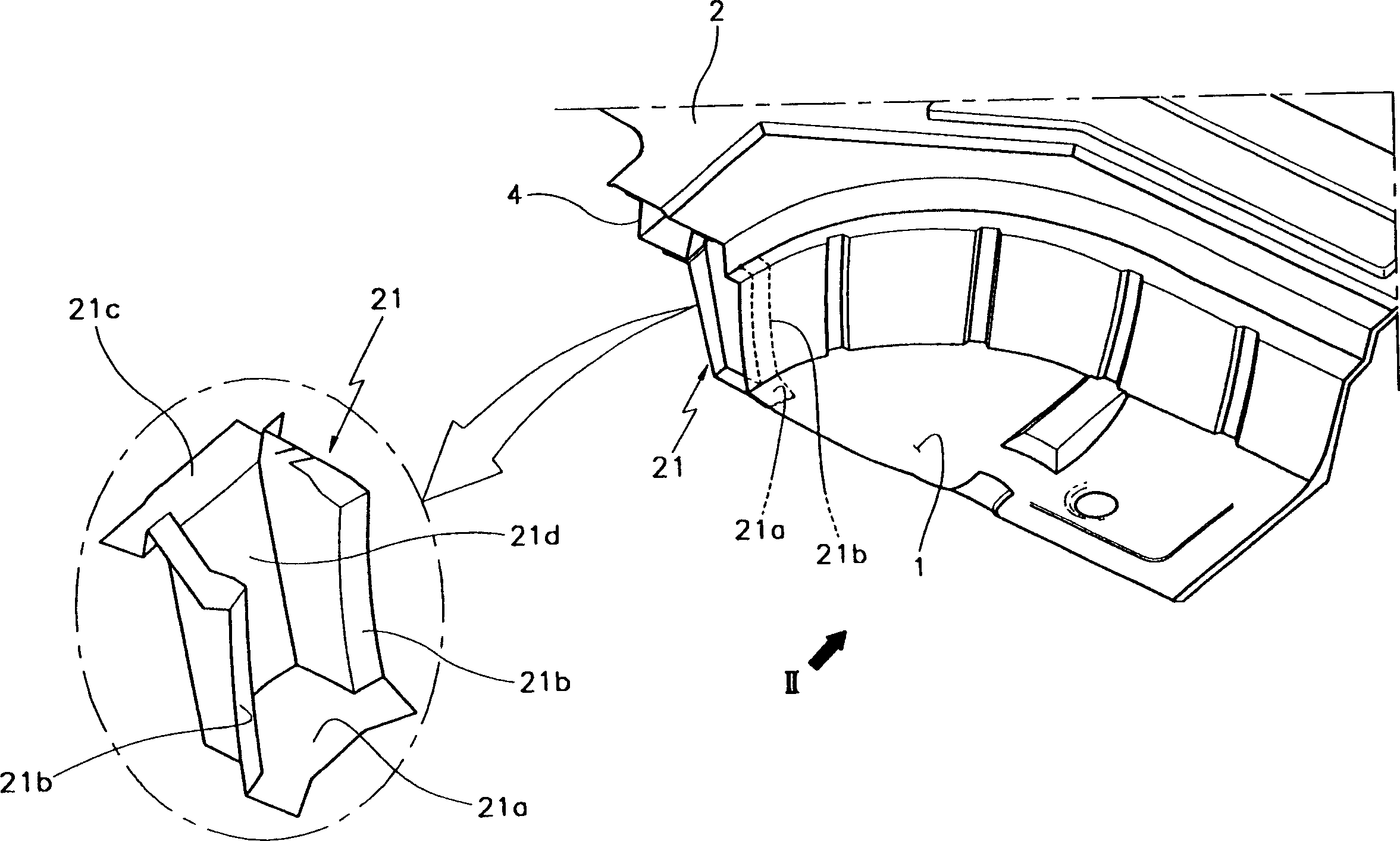
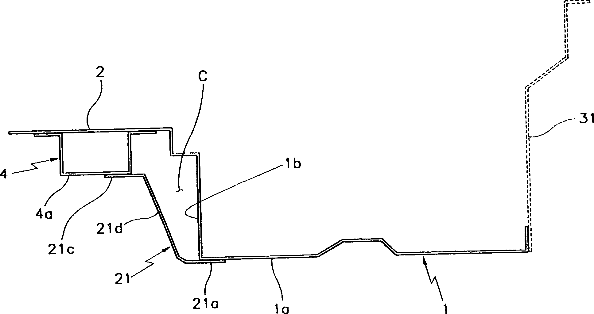
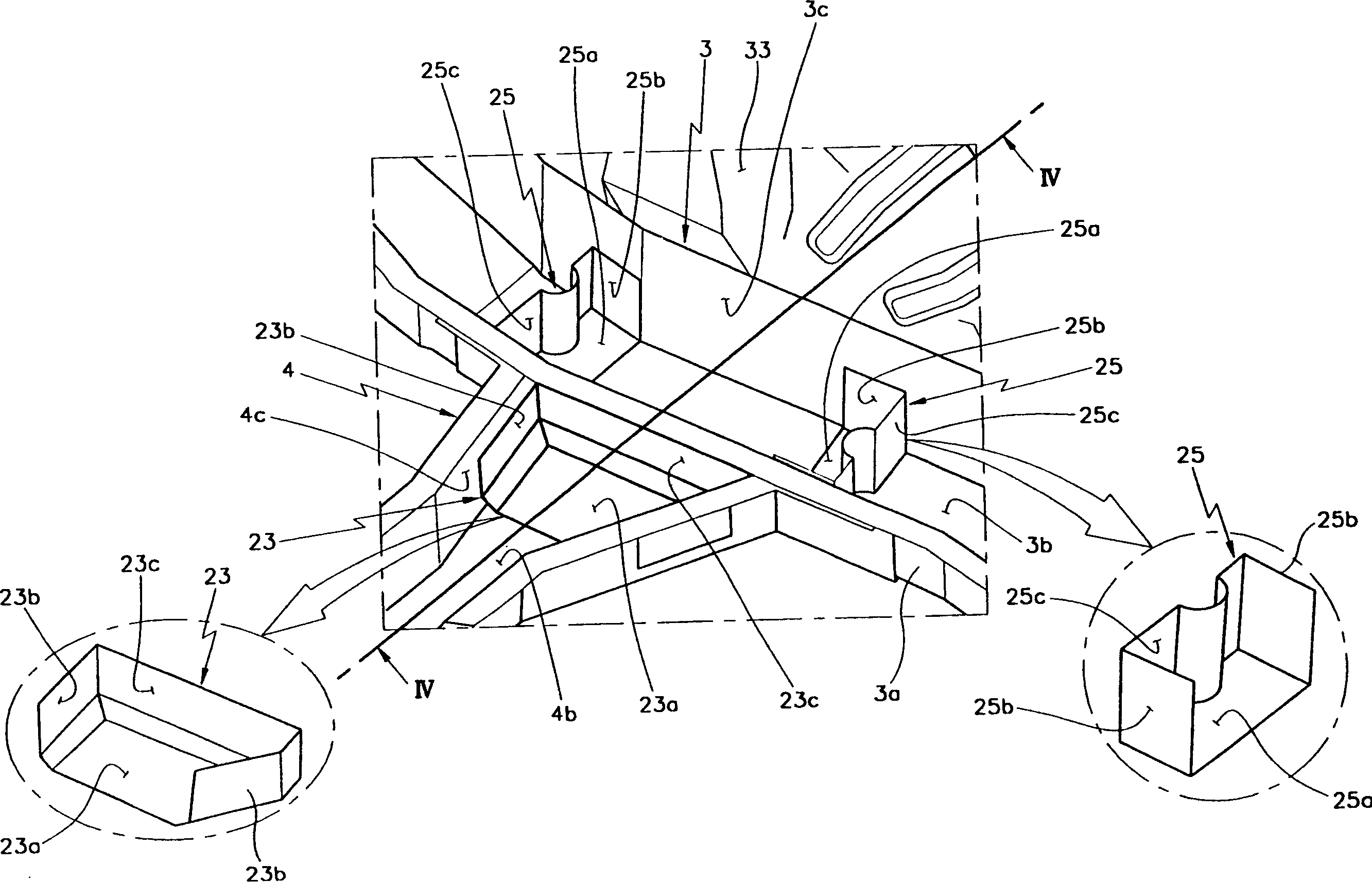
[0016] Such as figure 1 and 3 As shown, the rear floor component structure of the vehicle includes a rear floor 2 with a spare wheel space 1 at the rear of the vehicle. There is also a pair of rear floor side beams 3, each of which is located below the rear floor 2 along both sides in the longitudinal direction of the vehicle and is welded to the bottom surface of the rear floor 2. A rear floor cross member 4 is placed at intervals from the spare tire space 1 to the front of the vehicle, and crosses the rear floor 2 along the vehicle width direction, wherein the two ends of the re...


PUM


Abstract

The rear floor part structure for a vehicle includes a rear support bracket disposed between a spare-tire compartment and a rear floor cross member, a cross member bracket mounted at a coupling part of the rear floor cross member and rear floor side member by welding, and a pair of side member brackets disposed to face each other and inserted by being welded inside the rear floor side member near the part where the rear floor cross member couples with the rear floor side member is disclosed. The structure constructed above is configured to reinforce the rigidity of the vehicle body, thereby limiting the amount of thrust placed on the rear floor part toward the front of the vehicle when a rear collision occurs.

Description

[0001] Cross References to Related Applications [0002] This application claims priority from Korean Patent Application No. 10-2003-0032223 filed May 21, 2003, the disclosure of which is incorporated herein by reference in its entirety. technical field [0003] The present invention relates to a rear floor member structure of a vehicle for enhancing the rigidity of the vehicle when a rear collision occurs. Background technique [0004] In the event of a rear-end collision, the force of the impact is likely to propel the body toward the front of the vehicle, causing fuel to leak from the damaged fuel tank and injuring rear-seat passengers. [0005] Therefore, it is important to ensure that the rear of the vehicle has sufficient rigidity in the event of a rear collision. Contents of the invention [0006] An embodiment of the present invention provides a rear floor component structure of a vehicle, which is used to increase the support rigidity of the spare tire space of t...

Claims


Application Information

Patent Timeline
Patent Type & Authority Applications(China)
IPC IPC(8): B62D25/08B62D25/20
CPCB62D25/087B62D25/2027B62D25/20
Inventor 金璂畅
Owner HYUNDAI MOTOR CO LTD
Features
  • R&D
  • Intellectual Property
  • Life Sciences
  • Materials
  • Tech Scout
  • Unparalleled Data Quality
  • Higher Quality Content
  • 60% Fewer Hallucinations
Learn More