Bend operating apparatus for endoscope

An operating device, endoscope technology, applied in the direction of endoscope, application, medical science, etc., can solve problems such as operation failure, achieve the effect of preventing wire damage and enhancing bending operability

Inactive Publication Date: 2005-02-09
FUJI PHOTO OPTICAL CO LTD
View PDF1 Cites 13 Cited by
  • Summary
  • Abstract
  • Description
  • Claims
  • Application Information

AI Technical Summary

Problems solved by technology

[0005] However, when the pulley on which the wire is wound is operated to rotate, the wire is caught in the pulley, and there is a fear of causing operational failure

Method used


Image

  • Bend operating apparatus for endoscope
  • Bend operating apparatus for endoscope
  • Bend operating apparatus for endoscope

Examples


Embodiment Construction

[0020] Preferred embodiments of a bending operation device for an endoscope according to the present invention will be described below with reference to the accompanying drawings.

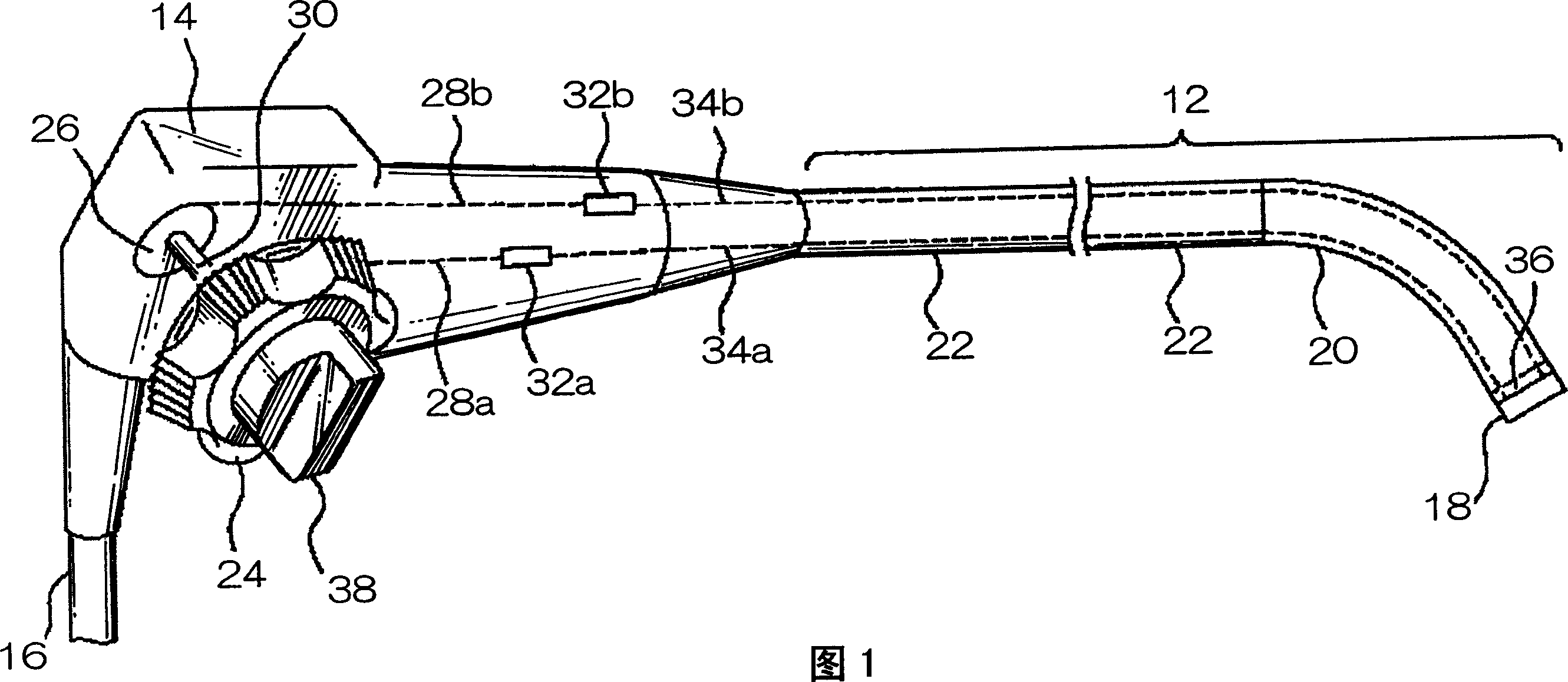
[0021] Fig. 1 is a schematic diagram of an endoscope to which a bending operation device according to the present invention is applied.

[0022] As shown in Figure 1, the endoscope mainly includes: an insertion part 12 inserted into a body cavity, a hand operation part 14 arranged at and connected to the bottom end part of the insertion part 12, and a hand operation part 14 extending from the hand operation part 14 and connected Universal cord member 16 to light source and processor (not shown in figure).

[0023] The insertion member 12 is composed of a tip portion 18, a bent portion 20, and a flexible portion 22, and the bent portion 20 is configured to be bendable at least up and down, or at least leftward and rightward. The bending portion 20 is bent by turning an angle knob 24 provided at the...


PUM


Abstract

The curving operation device of an endoscope is provided with the pulley 26 to be turned by an angle knob 24 and a groove 46 in a helical shape is formed on the outer peripheral surface of the pulley 26. The proximal end parts of a pair of traction wires 28a and 28b are wound from the end parts 46a and 46b of the groove 46 to the groove 46. The distal parts of the traction wires 28a and 28b are extended from the pulley 26 and connected via connecting members 32a and 32b to angle wires 34a and 34b. The traction wires 28a and 28b are constituted by twisting the plurality of wires 56 in the same direction as the winding direction of the groove 46.

Description

technical field [0001] The present invention relates to a bending operation device for an endoscope, and more particularly, to a bending operation device for bending a bending portion of an insertion member of an endoscope to a desired direction following a rotation operation of an angle knob. Background technique [0002] The medical endoscope is provided with an insertion part inserted into a body cavity, and a curved part is provided near the tip of the insertion part. The curved portion is curved up and down or left and right by a turning operation of an angle knob provided at the hand operation part. That is, the endoscope is provided with a bending operation device for bending the bending portion as the angle knob is rotated. [0003] The bending operating device is composed of a pulley rotatably operated by an angle knob and a pair of pull wires whose bottom end portions are wound along grooves of the pulley. The top end of the guy wire is connected to the angle wir...

Claims


Application Information

Patent Timeline
Patent Type & Authority Applications(China)
IPC IPC(8): A61B1/00A61B1/005
CPCA61B1/0051
Inventor 樋野和彦
Owner FUJI PHOTO OPTICAL CO LTD
Why Eureka
Try Eureka