Lightened rim for a bicycle wheel and method for manufacturing such a rim

A technology for bicycles and rims, applied in the field of lightening rims, can solve the problems of reducing, not allowing consistent material removal, and not fully satisfying the weight.

Active Publication Date: 2005-02-09
CAMPAGNOLO SRL
View PDF2 Cites 13 Cited by
  • Summary
  • Abstract
  • Description
  • Claims
  • Application Information

AI Technical Summary

Problems solved by technology

[0012] A disadvantage of the known solution is that the curve progression on the thickness variation do

Method used


Image

  • Lightened rim for a bicycle wheel and method for manufacturing such a rim
  • Lightened rim for a bicycle wheel and method for manufacturing such a rim
  • Lightened rim for a bicycle wheel and method for manufacturing such a rim

Examples


Embodiment Construction

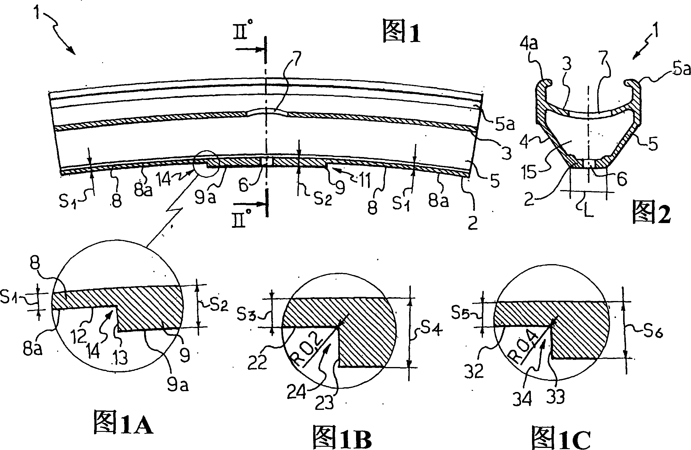
[0035] The wheel rim of the present invention is formed by extruding an aluminum alloy rod. The rod is formed into a circle, usually by calendering, and its ends joined by welding. Overall the rim indicated by 1, in Figure 9 and Figure 10 is shown in , where it is applied to two bicycle wheels W, W' having different spoke arrangements. The bicycle wheel W, W' already described is formed by a peripheral rim having an annular profile or rim 1, a central hub 18, 18' and spokes 19, 19', which are connected to the hub 18 , 18' and rim 1. FIG. 1 shows a section of such a rim 1 in longitudinal section, while FIG. 2 shows it in cross section.

[0036] As is clearly seen in the cross-sectional view of Figure 2, the rim 1 consists of two side walls 4, 5 connected at one end by a circumferential inner wall 2, known as a lower bridge, and at an intermediate point Connected by the peripheral outer wall 3 , known as the upper bridge, an essentially upwardly turned A-shaped cross sectio...


PUM


Abstract

This document describes a rim (1) for a bicycle having a lower bridge (2; 42) comprising a lower spoke area (8) whose thickness (S1; S3; S5) is smaller than that of the spoke attachment area (9 )thickness of. The increase in thickness from the lower spoke area (8) to the spoke attachment area (9), and the decrease in thickness between the spoke increase area (9) and the lower spoke area (8), has a very sharp progression and an acute corner (14 , 11; 24; 34; 64).

Description

technical field [0001] The invention relates to a lightened rim for a bicycle wheel and a method of manufacturing the rim. Background technique [0002] As is well known, bicycle wheels are formed from a peripheral rim or rim, a central hub and a plurality of spokes connecting the hub to the rim. [0003] The rim generally consists of two side walls connected or joined at one end by a circumferential inner wall or lower bridge and at an intermediate point by a circumferential outer wall or upper bridge to form a substantially Upturned A-section. The circumferential outer part of the side wall is usually provided with an outer edge forming a channel for the attachment of the tire, whereas the circumferential inner part of the side wall forms, together with the lower and upper bridges, a chamber for the attachment of the spokes. [0004] On the lower bridge, or inner wall, there are seats that serve as connections for the spokes. These seats usually consist of holes or eith...

Claims


Application Information

Patent Timeline
IPC IPC(8): B60B21/00B60B21/02B60B21/06
CPCB60B1/0215B60B1/003B60B2900/311B60B21/04B60B21/062B60B21/025
Inventor 毛里齐奥·帕萨罗托
Owner CAMPAGNOLO SRL
Why Eureka
Try Eureka