Cross-thread register sharing technique

A register and physical register technology, applied in memory systems, instruments, multiprogramming devices, etc., can solve the problem of reducing the number of free list entries, and achieve the effect of increasing hardware costs

Inactive Publication Date: 2012-10-10
INTEL CORP
View PDF0 Cites 0 Cited by
  • Summary
  • Abstract
  • Description
  • Claims
  • Application Information

AI Technical Summary

Problems solved by technology

[0008] figure 1 The prior art example of maximizes the free list size available to a particular thread, but requires the use of additional hardware, the ROB, to reallocate registers in the free list
on the other hand, figure 2 The prior art example of allows reallocating registers in the free list without using ROBs, but reduces the number of free list entries available to a single thread

Method used


Image

  • Cross-thread register sharing technique
  • Cross-thread register sharing technique
  • Cross-thread register sharing technique

Examples


Embodiment Construction

[0023] Embodiments of the invention relate to microprocessor architecture. More specifically, embodiments of the invention relate to register sharing techniques within microprocessors for multi-threaded instructions that facilitate mapping an optimal number of physical registers to a desired number of logical registers without incurring A lot of hardware overhead.

[0024] In at least one embodiment of the invention, a technique is used that incurs the hardware cost associated with the hard partition register sharing technique, but makes more registers available to another thread when one thread sleeps .

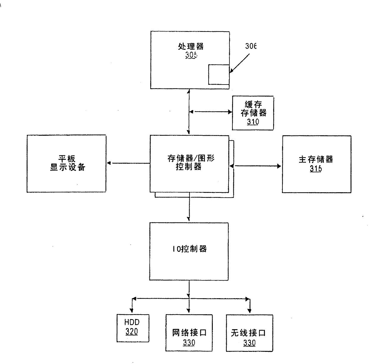
[0025] image 3 A computer system is shown in which at least one embodiment of the invention can be used. Processor 305 accesses data from cache memory 310 and main memory 315 . exist image 3 Shown in the processor 306 is an embodiment of the present invention. However, other embodiments of the invention may be implemented in other devices within the system, such as i...


PUM


Abstract

A technique for sharing register resources within a microprocessor. Embodiments of the invention pertain to a register sharing technique within a microprocessor for rnultiple-threads of instructions that facilitates an optimal number of physical registers to be mapped to a desired numiber of logical registers without incurring significant hardware overhead.

Description

technical field [0001] The present invention relates to microprocessor architecture. More specifically, the present invention relates to techniques for sharing register resources within a microprocessor. Background technique [0002] In a typical high-performance superscalar microprocessor, one performance-enhancing technique is register renaming, in which logical registers referenced by instructions are mapped onto a larger set of physical registers. This physical register map helps eliminate false dependencies that can exist in logical register maps. Traditionally, a structure such as the register alias table (RAT) stores the "logical to physical" mapping, while another structure, such as the free list table ("freelist"), is left unused or "free " until they are allocated and used by the renaming unit. [0003] In a multi-threaded processor capable of executing several threads simultaneously, the technique for allocating physical registers from a free list may use a har...

Claims


Application Information

Patent Timeline
Patent Type & Authority Patents(China)
IPC IPC(8): G06F9/38G06F9/46G06F9/30G06F9/318
CPCG06F9/3851G06F9/30181G06F9/384
Inventor 尼古拉斯·G·萨姆拉安德鲁·S·黄
Owner INTEL CORP
Why Eureka
Try Eureka