Bipolarized antenna

A dual-polarized antenna and symmetrical line technology, which is applied in directions such as antenna unit combinations with different polarization directions, can solve problems such as narrow distances

Active Publication Date: 2005-03-09
广州埃信科技有限公司 +1
View PDF9 Cites 47 Cited by
  • Summary
  • Abstract
  • Description
  • Claims
  • Application Information

AI Technical Summary

Problems solved by technology

This radiator cannot be made with cheap light printed circuit boards because the distance between the conductors of

Method used


Image

  • Bipolarized antenna
  • Bipolarized antenna
  • Bipolarized antenna

Examples


Embodiment Construction

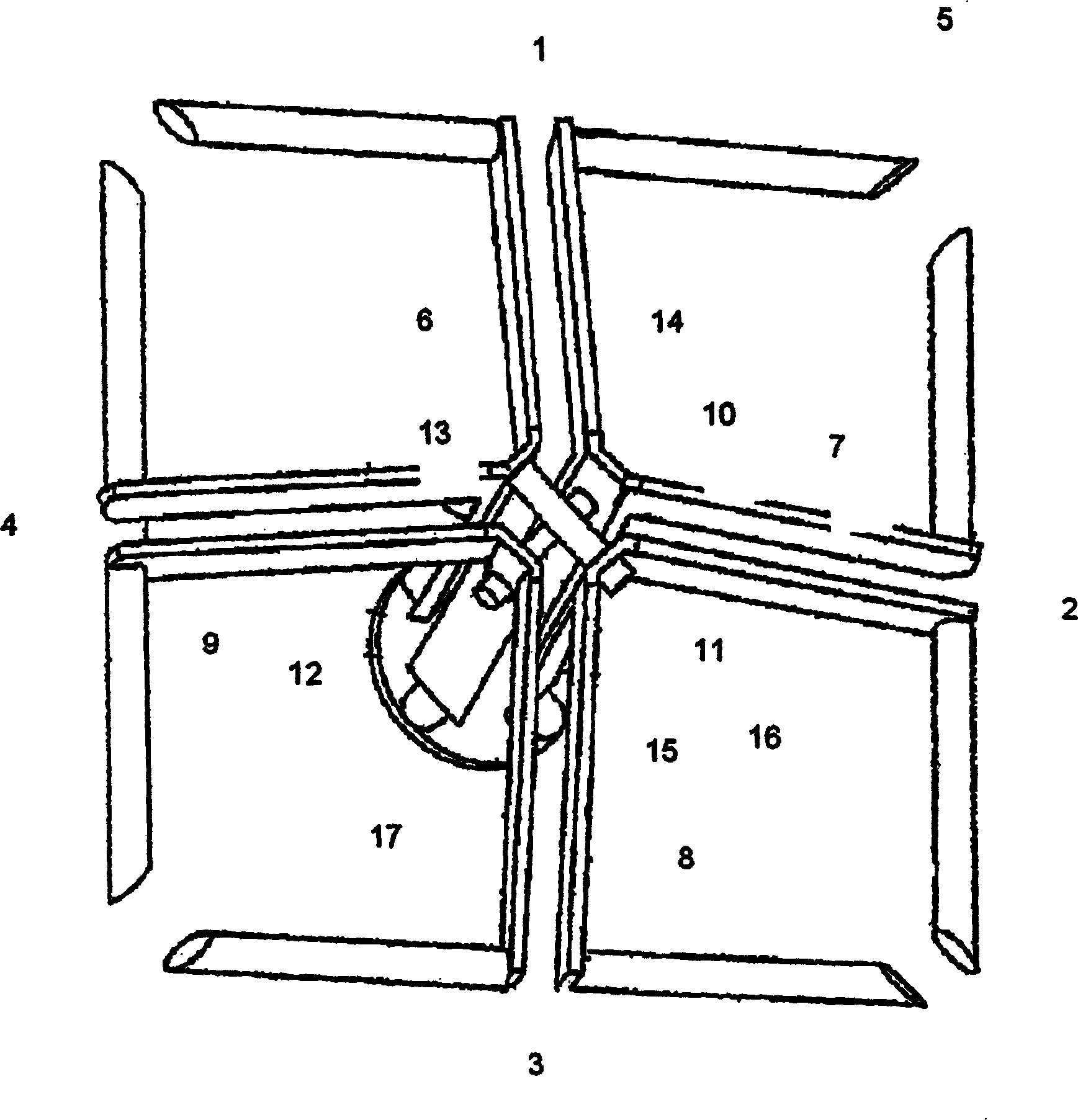
[0032] Embodiments of the present invention are now described in conjunction with the accompanying drawings. In order to clarify the difference between this invention and the known dipole radiator, the radiator is shown in Fig. 1. The known antenna contains four dipoles 1-4, which are more It is suitable to be arranged on the reflector 5, and the top view of its structure is a dipole square array. The dipole 1-4 is fed through the symmetrical line 6-9, the first end of the symmetrical line is connected to the dipole 1-4 and energized, and the second end is connected to the 10-13th of the two unbalanced transformers The ends are connected and powered on. The power feed of the two dipole halves opposite to each other is transmitted by coaxial cables through small needle-like electric bridges 14 and 15 (in figure 1 not shown in ). The first ends of these bridges are connected to the ends 10 and 13 of the balun and energized. Their second ends 16 and 17 are seated in holes adj...


PUM


Abstract

A duplex polarization antenna includes a radiation array set on a reflection earth plate, four support conductors constituting two mutual vertical unbalanced transformers and supporting the radiation array on the reflection earth plate. The radiation array is formed by four equivalent conducting rings with symmetric lines and their heads and tails are connected, each forms a branch of the ring and a branch of a cross slot. The cross conductor has four symmetric lines, two of which belong to the conduction rings, the other two are the diagonal lines of cross conductors. The support conductors are connected to the diagonal lines of the earth plates and the cross conductors, the activated radiation array has two mutual vertical electromagnetic field owning vector E parallel to the diagonal.

Description

technical field [0001] The present invention relates to a dipole antenna, more specifically, the present invention relates to transmitting or receiving two orthogonal poles, such as vertical and horizontal, + / - 45 degree oblique angle, or two circular poles. In today's era of heavy use of satellite broadcasting and mobile phone communications, there is a growing demand for such an easy-to-manufacture dual-polarized antenna. Background technique [0002] In the dual-polarization radiating unit system, people have invested considerable manpower and material resources in extensive and in-depth research, and several dipole antennas have come out, but basically each of them requires a large number of components, otherwise it will be Defects such as low reception rate or low frequency bands are generated. In the prior art, for example, US4922263, EP0685900 A1, US6008763 and US6018319 all describe slot antennas and patch antennas for transmitting or receiving two crossed poles. A...

Claims


Application Information

Patent Timeline
IPC IPC(8): H01Q21/24H01Q21/26
Inventor 艾提奥
Owner 广州埃信科技有限公司
Why Eureka
Try Eureka