Forming method of electric connector

An electrical connector and molding method technology, applied in the field of electrical connector molding, can solve problems such as inability to ensure terminal coplanarity, achieve good technical interaction, reduce manufacturing risks, and improve product qualification rates.

Inactive Publication Date: 2005-03-23
王道前 +1
View PDF0 Cites 0 Cited by
  • Summary
  • Abstract
  • Description
  • Claims
  • Application Information

AI Technical Summary

Problems solved by technology

[0005] In order to solve the above-mentioned problem that the existing electrical connector molding method cannot ensure the coplanarity of the terminals, the present invention provides a molding method of the electrical connector, which can effectively improve the normal position and coplanarity of the conductive terminals caused by the abnormal deformation of the insulating body. Improves mechanical and electrical properties by eliminating surface defects

Method used


Image

  • Forming method of electric connector
  • Forming method of electric connector
  • Forming method of electric connector

Examples


Embodiment approach

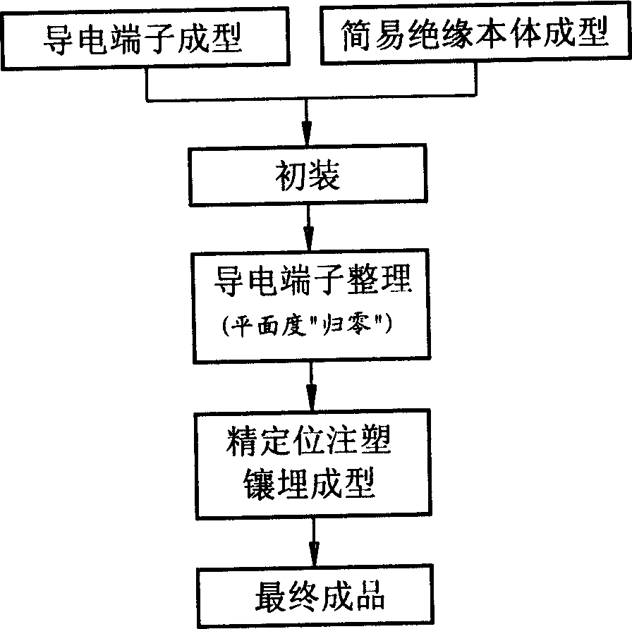
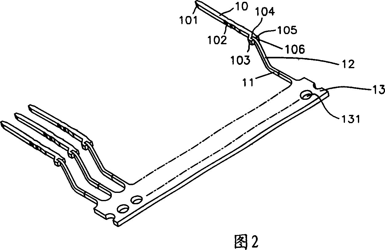
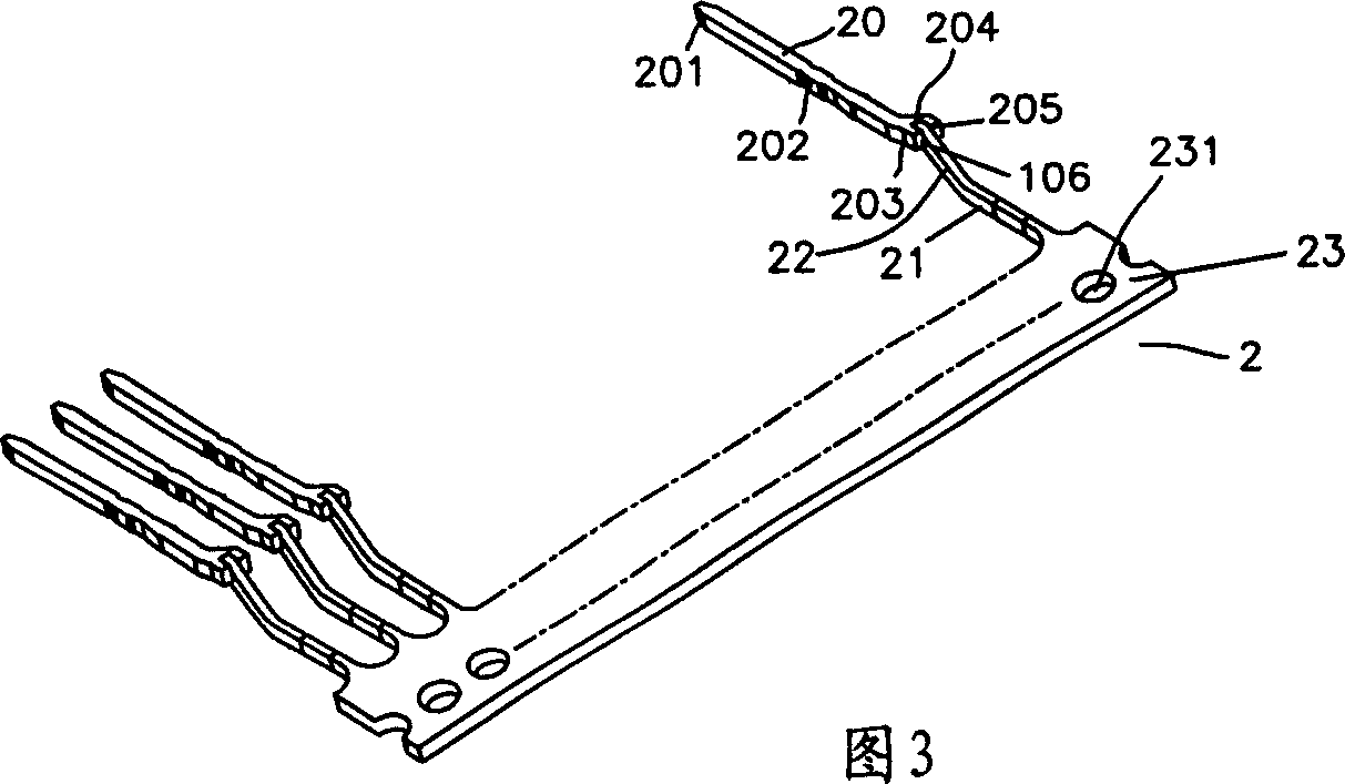
[0026] see figure 1 The flowchart of the forming method of the electrical connector of the present invention is shown, the present invention is to first punch the conductive terminal strips 1 and 2 of the electrical connector (refer to Fig. 2, shown in 3); 3 for injection molding (refer to Figure 4 shown); then insert the punched terminals 2 into the terminal receiving slot 31 of the simple insulating body 3, then cut off the tail material of the tape, and then insert the punched terminals 1 into the simple insulating body 3 The other row of terminals is accommodated in the through groove 36, and the tailings are not cut off, and then the positioning holes on the tail of the terminal 1 and the positioning grooves of the upper and lower molds are used for embedding and fine positioning molding, and finally the tailings are uniformly cut off. After the final step is completed Promptly constitute a concrete embodiment that the inventive method is made (with reference to Figur...


PUM


Abstract

The invention relates to a forming method of the electric coupler. The electric coupler is made by initial loading steps, electric terminal sorting steps and fine positioning injection moulding inlaying forming steps after the preparatory steps of electric terminal forming and simple insulating matrix forming. After the electric terminal sorting steps, make use of the plastic structure to orientate the terminals, make the planeness return to zero and then carry out the injection moulding inlaying forming. By this way, the simple insulating matrix formed for the first time is put in the final insulating matrix, which can avoid the shrinkage distortion and the excess of hour angle increment of the planeness. In addition, the orientation of the plastic component can reach the precise planeness of the control terminal jointing plane, meets the high requirement to the planeness in today's industry, reduces the manufacturing risk, increases the up-to-standard rate of the products and forms good technological interaction with the related industry.

Description

【Technical field】 [0001] The invention relates to a molding method of an electrical connector, in particular to an effective method for solving the problem of poor flatness of SMT electrical connectors in the current industry through the first initial assembly of terminals and the second injection molding. 【Background technique】 [0002] Nowadays, the thickness of the steel mesh (mesh screen) used for the circuit board used to accept the electrical connector in the industry is mostly between 0.12 and 0.20mm according to the precision of the product. The electrical connector installed on the circuit board usually requires its soldering. The coplanarity of the pins is controlled within 0.10mm. With the development of electrical connectors towards fine pitch (Fine Pitch), many upstream customers even require the coplanarity to be controlled within 0.05mm, although a few companies in the industry have promised to meet the requirements , but in fact the defect rate has remained h...

Claims


Application Information

Patent Timeline
IPC IPC(8): H01R13/40H01R43/00
Inventor 王道前施东升
Owner 王道前
Why Eureka
Try Eureka