
Draft device

A traction device and drafting technology, which is applied in the direction of drafting equipment, textiles and papermaking, and continuous winding spinning machines, etc., can solve the problems of not actively and effectively using the associated airflow, and achieve the effect of suppressing horizontal diffusion

Inactive Publication Date: 2005-04-06
MURATA MASCH LTD
View PDF0 Cites 6 Cited by
  • Summary
  • Abstract
  • Description
  • Claims
  • Application Information

AI Technical Summary

Problems solved by technology

However, this technique does not actively utilize the associated airflow to align the fibers with each other in the feed direction and cause the fibers to escape in the horizontal direction

Method used


Image

  • Draft device
  • Draft device
  • Draft device

Examples


Embodiment Construction

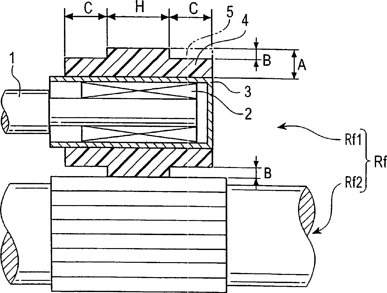
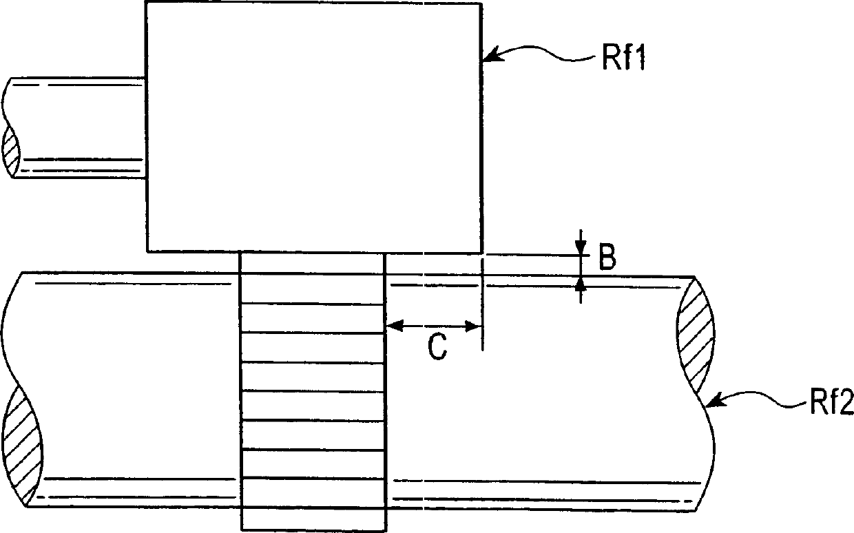
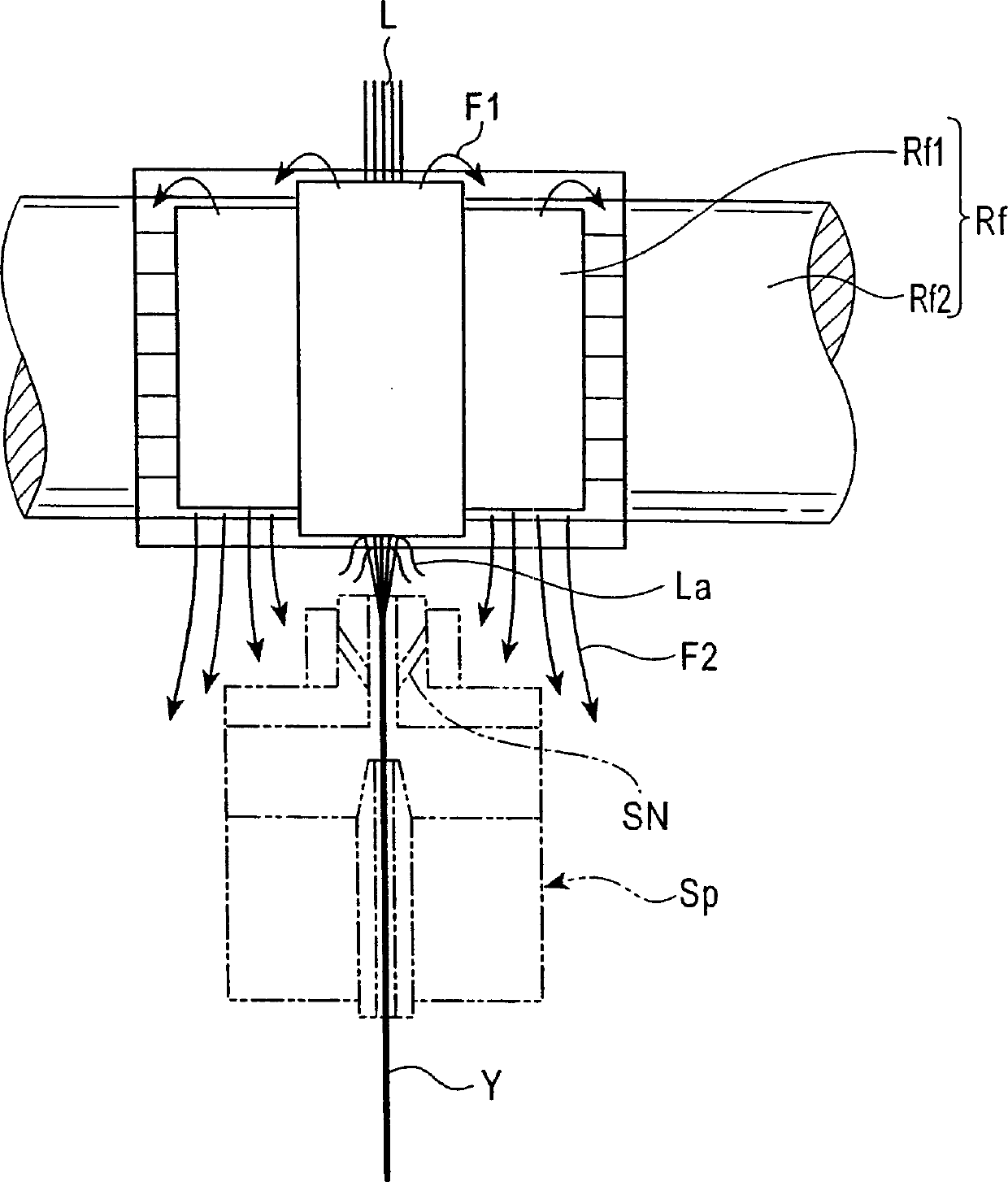
[0029] The present invention achieves the above object using the structure described below to obtain a traction device comprising a traction roller capable of reducing the negative influence of the accompanying air flow generated by the roller rotating at high speed while maintaining Clamping force, and can effectively use the associated air flow to suppress the spread of fiber bundles. A step is formed on each end of one of the rollers constituting the roller pair. An associated air flow generated by the rotation of the rollers passes through the steps. Furthermore, the air flow through the steps forms a barrier that prevents the fiber bundles that are fed and simultaneously drawn from spreading.

[0030] Next, an embodiment of the traction device according to the present invention will be described in detail with reference to FIGS. 1-9.

[0031] First, a spinning machine M to which the present invention is applied will be described with reference to FIG. 5 . A plurality o...


PUM


Abstract

It is an object of the present invention to provide a draft device DR including draft rollers which, when a draft device composed of a plurality of draft roller pairs is used, can reduce the adverse effect of associated air currents resulting from the rollers rotating at high speed while maintaining a gripping force and can effectively utilize the associated air currents to suppress the spread of a bundle of fibers L. The present invention provides a draft device DR including a plurality of roller pairs that pull a bundle of fibers L while feeding the bundle downstream, wherein associated air currents resulting from a roller constituting the roller pair are passed through ends of the roller, and gaps are provided which form air passages in which the air currents act as air flows forming a prevention wall that hinders spread of the bundle of fibers fed while being drafted.

Description

technical field [0001] The invention relates to a drawing device comprising a drawing roller for feeding a fiber bundle (also called sliver) and simultaneously drafting (this operation also called "drawing") said fiber bundle. Background technique [0002] As a kind of traditional drawing device, roller drawing device is well-known, and it is made of a plurality of roller pairs, and described roller pair is used for drafting sliver and simultaneously clamps described sliver and described sliver to downstream side supply. [0003] Moreover, the roller-type drawing device has a plurality of roller pairs, each roller pair is composed of an upper roller and a lower roller, and is arranged in the feeding direction of the sliver. In order to be able to draw the sliver, the roller pairs rotate at such different rotational speeds that the rotational speed of any one roller pair is slightly greater than that of the preceding roller pair. A traction bracket temporarily holds and sup...

Claims


Application Information

Patent Timeline
Patent Type & Authority Applications(China)
IPC IPC(8): D01H1/00D01H5/22D01H5/74D01H5/78
CPCD01H5/78
Inventor 太田成利
Owner MURATA MASCH LTD
Learn More