Sealed touch switch and process for making same

A technology of touch switch and manufacturing process, which is applied in the direction of electric switches, electrical components, circuits, etc., can solve the problems that touch switches are incompetent, and achieve the effect of increasing stability and reliability

Inactive Publication Date: 2005-04-06
陈光辉
View PDF1 Cites 9 Cited by
  • Summary
  • Abstract
  • Description
  • Claims
  • Application Information

AI Technical Summary

Problems solved by technology

For example, the radio touch switch for motorcycles works under such

Method used


Image

  • Sealed touch switch and process for making same
  • Sealed touch switch and process for making same
  • Sealed touch switch and process for making same

Examples


Example Embodiment

[0013] The present invention will be described in detail below in conjunction with the accompanying drawings:

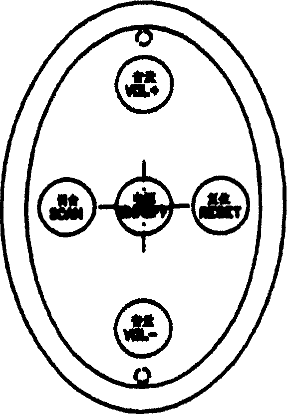
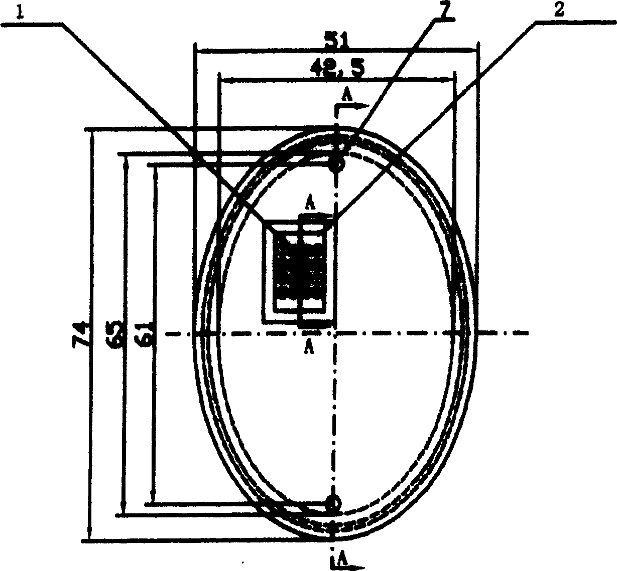
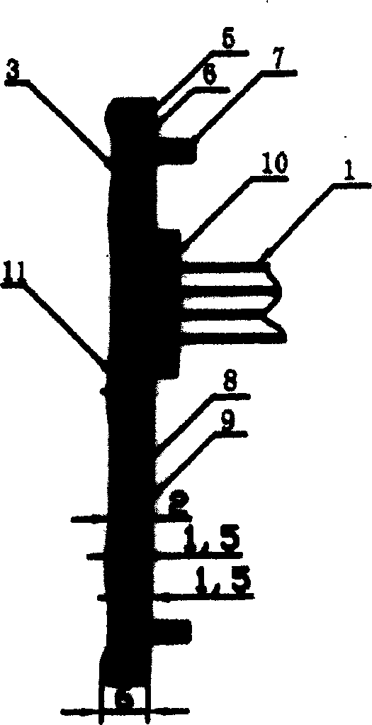
[0014] The specific embodiment of the present invention is a radio sealed touch switch used on a motorcycle. Five touch switch combinations 3 are sealed in an oval plastic box 8, and its surface layout is as follows figure 1 As shown, the power ON / OFF switch is centered, and the volume VOL+, the volume VOL-, the tuning SCAN, and the reset RESET are in sequence. figure 2 This is the bottom view of the plastic box 8 that was injection molded for the first time. The outline size is an ellipse with a major axis of 74 mm and a minor axis of 51 mm, with a lead hole 2, a screw hole 26 and a lead 1 reserved. image 3 It is a cross-sectional view of the sealed touch switch AA. The touch switch assembly 3 is sealed in the plastic box 8, the fixing screw 7 is exposed outside, the gasket 5 and the nut 6 are sealed in the plastic box 8, the lead 1 is led out by the lead hole 2, and...


PUM


Abstract

It is a sealed touch switch and its process, which comprises the following steps: first to inject and mold a plastic case with its inner shape same to the outer shape of the touch switch, wherein, the inner size of the plastic case is little more than the outer size of the touch switch; to put the touch switch into the plastic case for another injection molding to seal the boundary of the touch switch surface with plastic case; to fill the lead wire hole with plastic liquid to seal it to add the stability and reliability of the switch.

Description

technical field [0001] The invention relates to a sealed touch switch and its manufacturing technology. Background technique [0002] The patent application with the application number 02106698.1 was filed by Isao Miyashita of Japan. The name is a touch switch, which discloses the structure and use of the touch switch. Its purpose is to increase the reliability of the switch. In the embodiment, it is mentioned to provide a A kind of waterproof seal, mainly for the spring piece, the flexible cover and gasket made of plastics surround the spring contact piece to achieve sealing. It is a partial seal and has the function of waterproof and moisture-proof. Under normal environmental conditions, use this Touch switches are perfectly fine. In poor environmental conditions, in the open air, wind, sun, rain, bumps, vibrations and other harsh environmental conditions, the requirements for waterproof, moisture-proof, and shock-proof are more stringent. Such as the touch switch of the...

Claims


Application Information

Patent Timeline
IPC IPC(8): H01H13/06H01H13/702
Inventor 陈光辉
Owner 陈光辉
Why Eureka
Try Eureka