

Cross beam of lamp stand of vehicle
A technology of beams and car lights, applied in searchlight transportation and other directions, can solve the problems of unsafe transportation, poor wind resistance, and large space occupation, and achieve the effect of safe transportation, strong wind resistance, and small space occupation.
- Summary
- Abstract
- Description
- Claims
- Application Information
AI Technical Summary
Problems solved by technology
Method used
Image

Examples
Embodiment Construction
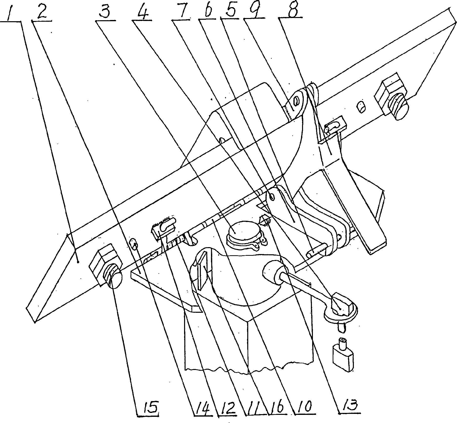
[0013] In order to further understand the characteristics and effects of the present invention, the following embodiments are given as examples, and detailed descriptions are as follows in conjunction with the accompanying drawings, please refer to figure 1 .
[0014] Such as figure 1 Shown: this lighting car light frame beam is made of cross bar 1, fixed plate 2, vertical shaft 3, handle 4, connecting rod 6, fixed shaft 7, wrench 8, hinge 10, spring 11, fixed hook 12, adjusting screw 13 and The light frame is composed of fixing screws, the crossbar 1 and the fixed plate 2 are connected by a hinge 10, the crossbar 1 and the fixed plate 2 are respectively welded with two hinges in the middle through the shaft, the crossbar 1 can rotate around the fixed plate 2 at a certain angle, The horizontal bar (1) is made of rectangular steel pipe, the vertical shaft 3 is fixed on the fixed plate 2, the horizontal bar 1 and the fixed plate 2 are driven to rotate on the horizontal plane th...
PUM
 Abstract
Description
Claims
Application Information