
Mounting structure of bumper beam

A technology for installing structures and bumpers, applied in the directions of bumpers, transportation and packaging, vehicle safety arrangements, etc., can solve the problem of low weight and high strength of bumper beams, insufficient absorption of impact energy, and reduced bending strength of bumper beams, etc. problems, to achieve the effect of convenient vertical positioning, stable energy absorption, and prevention of vertical deformation

Inactive Publication Date: 2005-06-01
SUZUKI MOTOR CORP +1
View PDF2 Cites 20 Cited by
  • Summary
  • Abstract
  • Description
  • Claims
  • Application Information

AI Technical Summary

Problems solved by technology

However, the reduction in material thickness reduces the bending strength of the entire bumper beam
Therefore, there is a limit in achieving both low weight and high strength of the bumper beam
[0009] On the other hand, in the structure described in Japanese Patent Provisional Publication No. 2000-85496, since the reinforcement is formed with only one steel pipe, the absorption of impact energy is insufficient.

Method used


Image

  • Mounting structure of bumper beam
  • Mounting structure of bumper beam
  • Mounting structure of bumper beam

Examples


Embodiment Construction

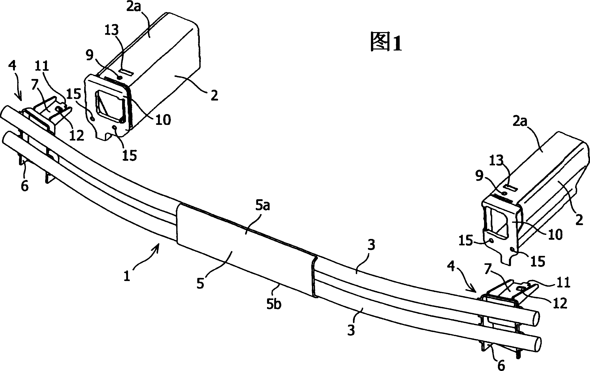
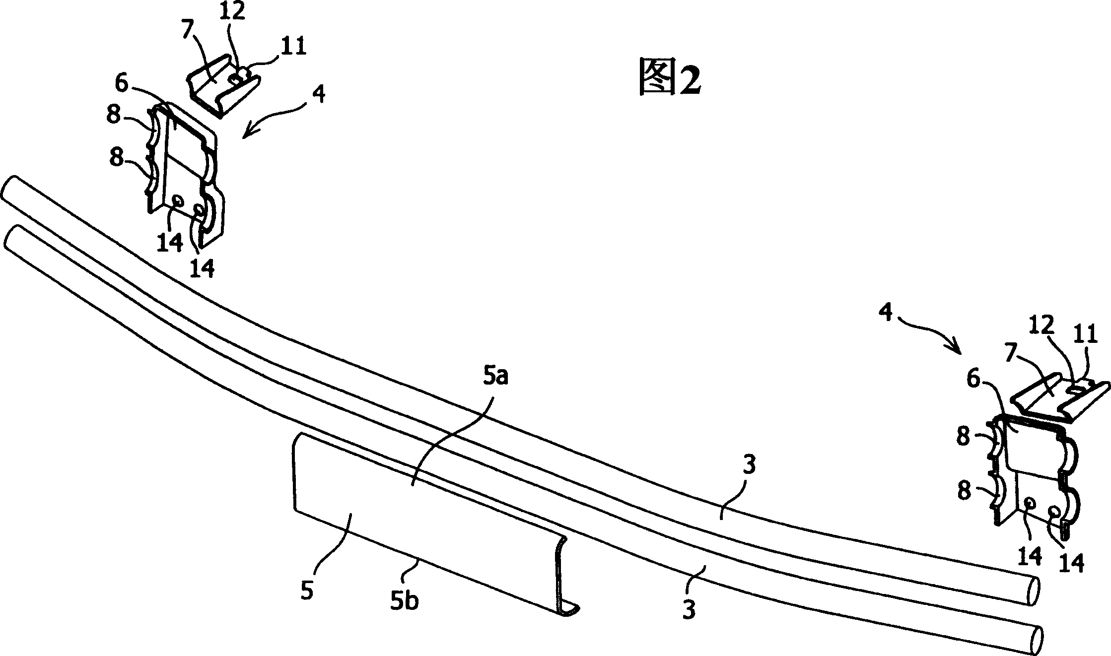
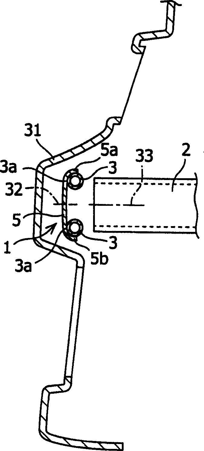
[0031] The following will combine Figure 1 to image 3 The best mode for carrying out the present invention will be described in detail. FIG. 1 is a perspective view of a bumper beam 1 before being mounted to a side member 2, and FIG. 2 is an exploded perspective view of the bumper beam 1 disassembled into individual components. image 3 is a sectional view of the bumper beam 1 mounted on the side member 2, where it is cut from the center portion in the vehicle width direction.

[0032] In this embodiment, the description is made for the case where the bumper beam 1 is composed of two tubes. Meanwhile, in the present embodiment, the description is made corresponding to a bumper beam mounting structure in which the bumper beam 1 is mounted on a lower portion in front of the vehicle.

[0033] In the bumper beam mounting structure shown in FIG. 1 , the bumper beam 1 is mounted on the side beam 2 on the side of the vehicle body. As shown in FIGS. 1 and 2, the bumper beam 1 has tw...


PUM


Abstract

Provided is a mounting structure of a bumper beam whose weight is reduced while ensuring sufficient strength. In a bumper beam mounting structure for mounting the bumper beam on at least one of the front part or the rear part of the side beam, wherein the side beam is located on both sides in the vehicle width direction and along the vehicle extending in the longitudinal direction of said bumper beam having two or more tubes each having a length at least equal to the distance between said side members, said tubes being arranged horizontally and one above the other, Thus, the outer surfaces of these tubes are located at the same position in the longitudinal direction of the vehicle, and the center position of the bumper beam in the height direction is substantially coincident with the center position of the side member in the height direction.

Description

technical field [0001] The present invention relates to a mounting structure for mounting a bumper beam on at least one of a front side and a rear side of a vehicle. Background technique [0002] There are bumpers on the lower part of the front and rear of the vehicle. Bumpers protect functional parts such as the body or lights in the event of a collision between the vehicle and other objects. There is a bumper beam at the rear of the bumper, which is used to absorb the impact energy when the body is hit by a collision. [0003] Bumpers come in many shapes, depending on the size of the vehicle. In addition, because the bumper also has the function of enhancing the design characteristics, corresponding to different car models, the bumper used also has a variety of different design shapes. Therefore, in order to match the shape of the bumper, there are also many types of bumper beams produced. [0004] In order to manufacture the bumper beam, materials such as steel sheets...

Claims


Application Information

Patent Timeline
Patent Type & Authority Applications(China)
IPC IPC(8): B60R19/04B60J5/06B60R19/12B60R19/18B60R19/24
CPCB60R19/12B60R19/18B60R19/24B60R2019/1826
Inventor 小林章高桥秀和裤田功铃木正晃
Owner SUZUKI MOTOR CORP
Learn More