Radio-controlled clock

A technology of radio and clocks, applied in the field of obtaining time information, can solve problems such as inability to guarantee, and achieve the effect of high working performance

Inactive Publication Date: 2005-06-15
ATMEL GERMANY +1
View PDF5 Cites 4 Cited by
  • Summary
  • Abstract
  • Description
  • Claims
  • Application Information

AI Technical Summary

Problems solved by technology

Users expect greater performance and ease of use in these often expensive devices, but at present this cannot be guaranteed or can only be achieved to a limited extent

Method used


Image

  • Radio-controlled clock
  • Radio-controlled clock
  • Radio-controlled clock

Examples


Embodiment Construction

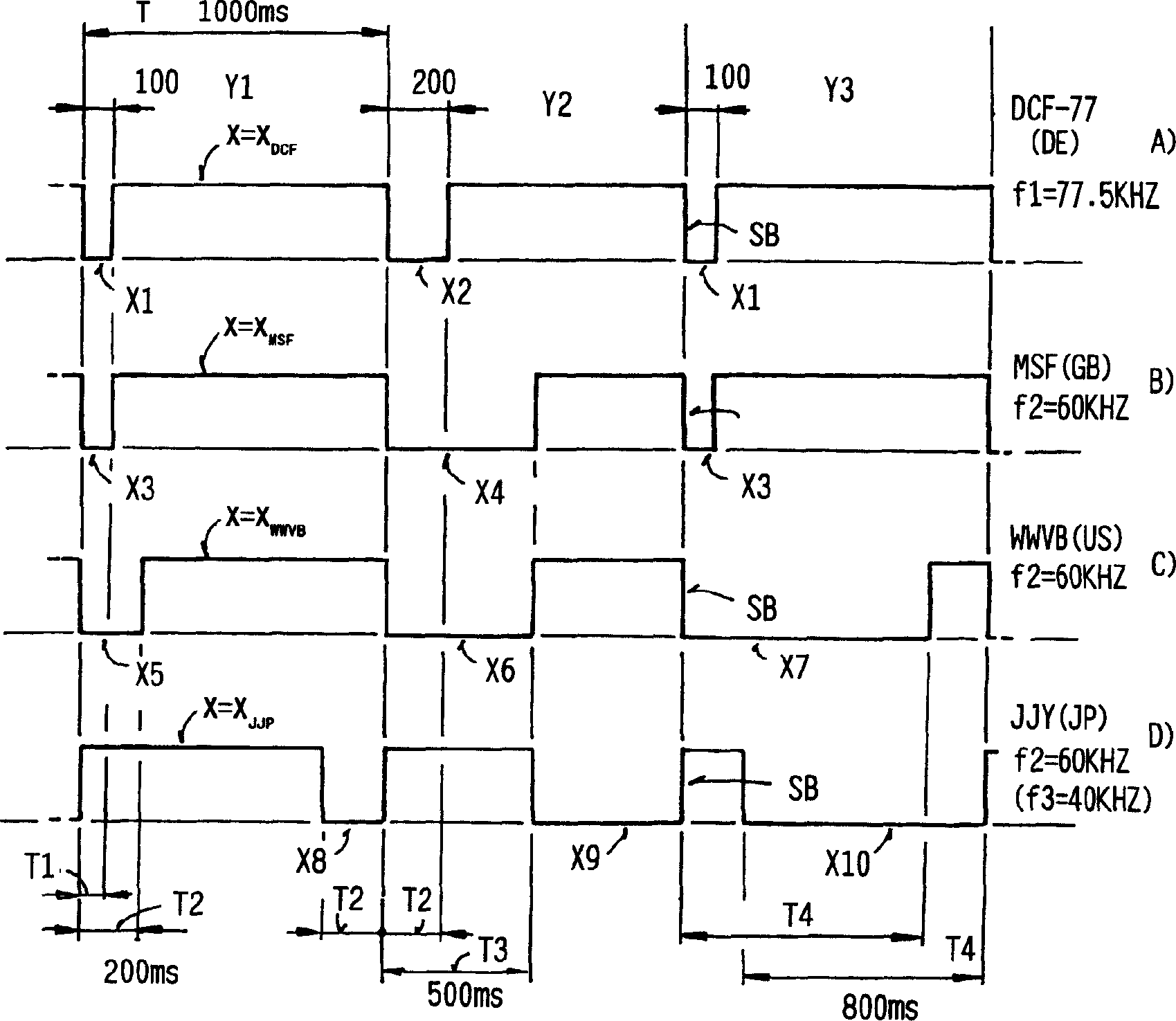
[0039] image 3 The method according to the invention is explained by means of a segment of a signal-time waveform diagram representing the timing signals of different timing transmitters. image 3 The waveform diagram in is only to represent different time scale signals according to the principle, so as to illustrate the difference between different time scale signals. image 3 The diagrams in are not suitable for simulating a dedicated code.

[0040] To illustrate the method according to the invention, each timing signal X of four different timing transmitters will be described. In this case, they involved the German time-scale transmitter DCE-77 ( image 3 (A)), British time scale transmitter MSF ( image 3 (B)), American time scale transmitter WWVB ( image 3 (C)) and Japanese time scale transmitter JJY ( image 3 (D)) time scale signal X DCF 、X MSF 、X WWVB 、X JJY .

[0041] image 3 Segments of these timing signals X are represented, wherein for example three c...


PUM


Abstract

The invention relates to a method for obtaining time information from a transmitted time stamp signal, which time stamp signal consists of a plurality of time frames of constant duration, wherein the received time stamp signal corresponds to the time at which the time stamp signal was sent. The time stamp transmitter is used to obtain the time information directly from the transmitted time stamp signal and the correspondence of the time stamp signal to the time stamp transmitter that sends the time stamp signal. The invention also relates to a receiving circuit for a radio timepiece and a radio timepiece.

Description

technical field [0001] The invention relates to a method for obtaining time information from a time stamp signal transmitted by a time stamp transmitter. The invention also relates to a receiving device for a radio timepiece and a radio timepiece. Background technique [0002] The transmission of the radio-controlled time information takes place by means of so-called time stamp signals (Zeitzeichensignale), which are transmitted by corresponding transmitters—hereinafter simply referred to as time stamp transmitters (Zeitzeichensender). A time stamp signal is to be understood as a short-duration transmitted signal, which is assigned the task of transmitting a reference time provided by a transmitter. In this case it involves a modulated oscillation, usually with several time stamps, which are only demodulated into one pulse which reproduces the transmitted reference time with a certain inaccuracy. [0003] The German long-wave transmitter DCF-77 is controlled by an atomic c...

Claims


Application Information

Patent Timeline
Patent Type & Authority Applications(China)
IPC IPC(8): G04G5/00G04R20/10H04J3/06
CPCG04R20/10
Inventor 霍斯特·黑夫纳罗兰·波洛尼奥汉斯-约阿希姆·赛勒
Owner ATMEL GERMANY
Why Eureka
Try Eureka