Check patentability & draft patents in minutes with Patsnap Eureka AI!

Data transfer circuit

A data transmission circuit and data technology, applied in data conversion, electrical digital data processing, digital memory information, etc., can solve problems such as uncertainty

Inactive Publication Date: 2005-06-15
LAPIS SEMICON CO LTD
View PDF1 Cites 1 Cited by
  • Summary
  • Abstract
  • Description
  • Claims
  • Application Information

AI Technical Summary

Problems solved by technology

[0008] However, the above-mentioned data transmission circuit has the following problem: when the write data WDT is written into the FIFO memory 1 from the PHS side, the count value CNT of the counter 2 read from the personal computer side will read an indeterminate count value CNT , so that the read read data RDT is more than the actual stored data
[0009] There is also the following problem: when the read data RDT is read from the FIFO memory 1 on the personal computer side, when the count value CNT of the counter 2 is read from the PHS side, an indeterminate count value CNT will be read, and the value exceeding the Write data WDT of blank area

Method used


Image

  • Data transfer circuit
  • Data transfer circuit
  • Data transfer circuit

Examples


Embodiment Construction

[0021] The above and other objects and novel features of the present invention can be fully understood when read in conjunction with the following description of the preferred embodiments with reference to the accompanying drawings. However, these figures are for illustration only, and are not intended to limit the scope of the present invention.

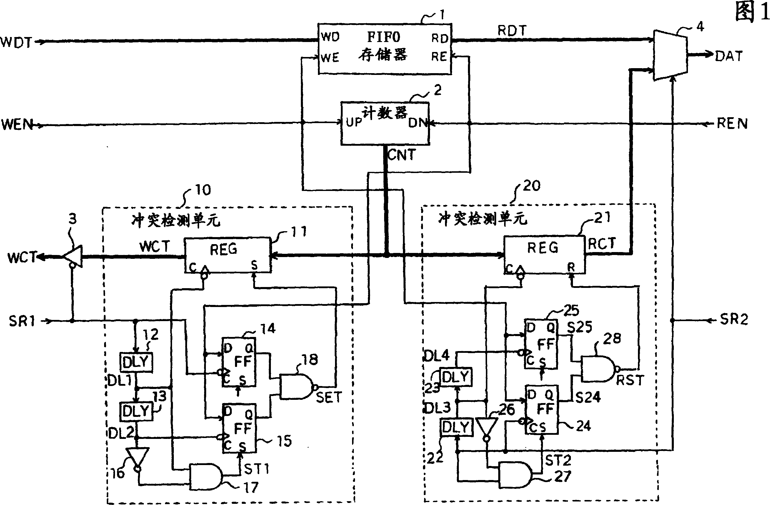
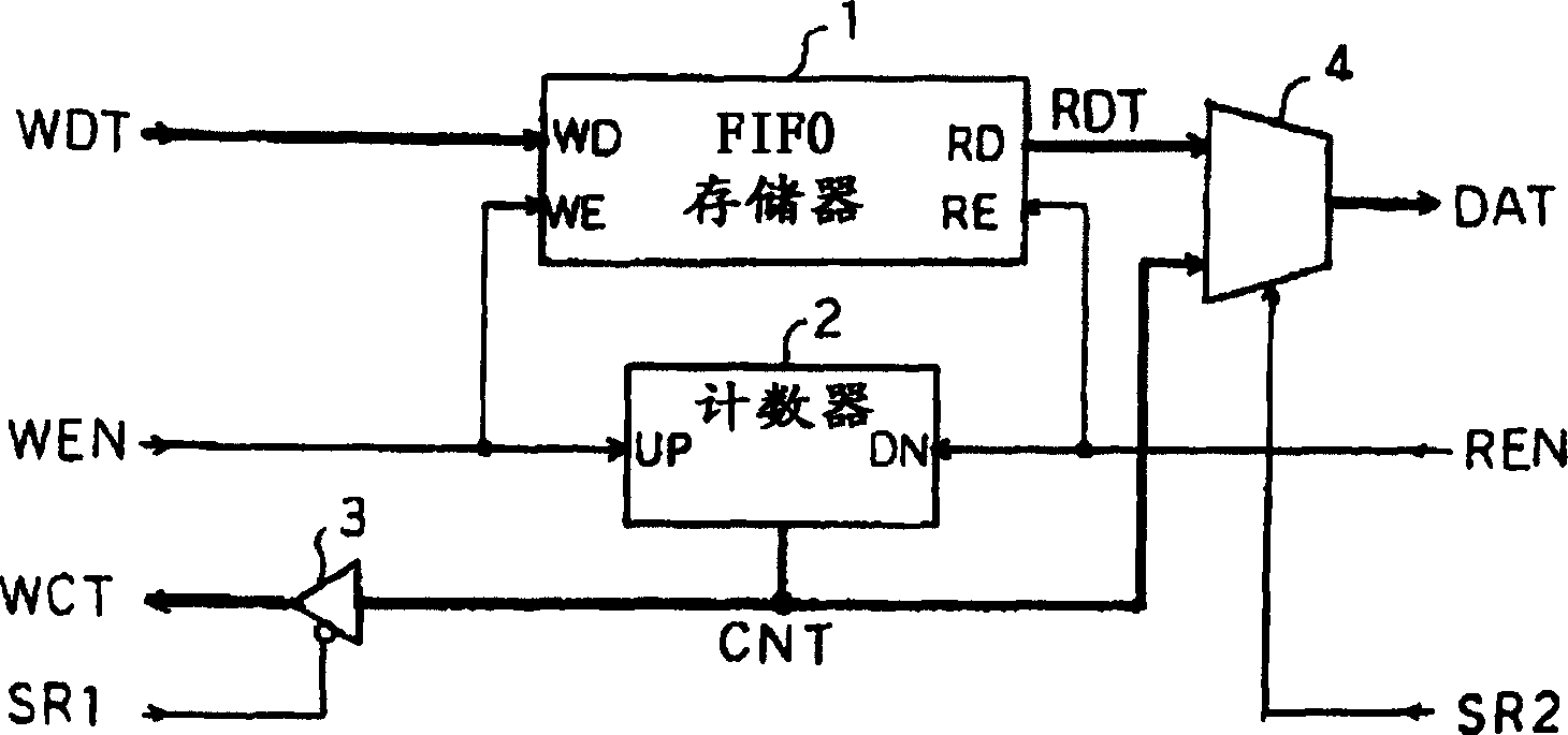
[0022] FIG. 1 is a block diagram showing a data transmission circuit of an embodiment of the present invention. Where and figure 2 Common components all use the same symbols.

[0023] The data transmission circuit is, for example, used to transmit data from a first device (such as a PHS) connected to the left side of the figure to a second device (such as a personal computer) connected to the right side. except with figure 2 In addition to the same FIFO memory 1 , counter 2 , buffer 3 and selector 4 , it also includes a conflict detection unit 10 and a conflict detection unit 20 .

[0024] The FIFO memory 1 sequentially stores t...


PUM


Abstract

The present invention aims to prevent data transmission errors caused by access conflicts between two devices. The solution is: in the conflict detection unit 10, when the second device is reading data from the FIFO memory 1, if the state readout signal SR1 for reading the count value of the counter 2 from the first device is detected, Then, regardless of the size of the count value of the counter 2, a value indicating that the FIFO memory 1 is full is output to the first device. In addition, in the collision detection unit 20, when the first device writes data to the FIFO memory 1, if the state read signal SR2 for reading the count value of the counter 2 from the second device is detected, regardless of the state of the counter 2 Regardless of the size of the count value, a value indicating that the FIFO memory 1 is completely empty is output to the second device.

Description

technical field [0001] The present invention relates to a data transmission circuit using a FIFO (First In First Out) buffer for data transmission. Background technique [0002] As such prior art, there is Patent Document 1, JP-A-2003-23469. [0003] figure 2 It is a structural diagram of a conventional data transmission circuit using a FIFO buffer, and it is a data communication card incorporated in, for example, data transmission between a PHS (Personal Handyphone System) and a notebook personal computer (hereinafter referred to as a personal computer) . [0004] This data transfer circuit, for example, is the one capable of transferring data from a PHS connected on the left side of the figure to a personal computer connected on the right side of the figure, and has a FIFO memory 1, a counter 2, a buffer 3 and a selector 4. [0005] The FIFO memory 1 sequentially stores write data WDT according to a write control signal WEN, and sequentially reads data from the beginnin...

Claims


Application Information

Patent Timeline
Patent Type & Authority Applications(China)
IPC IPC(8): G06F13/38G06F5/06G06F5/12G06F12/00G06F13/00G11C7/00
CPCG06F5/06G06F5/12G06F2205/123G06F2205/126G06F12/00G06F13/00
Inventor 品川德明
Owner LAPIS SEMICON CO LTD
Features
  • R&D
  • Intellectual Property
  • Life Sciences
  • Materials
  • Tech Scout
  • Unparalleled Data Quality
  • Higher Quality Content
  • 60% Fewer Hallucinations
Learn More