Clamp for slender object such as a cable

A technique for elongated objects, clips, used in the direction of electrical components, vehicle components, electrical circuits, or fluid lines

Inactive Publication Date: 2005-06-22
NEWFREY +1
View PDF4 Cites 5 Cited by
  • Summary
  • Abstract
  • Description
  • Claims
  • Application Information

AI Technical Summary

Problems solved by technology

Due to the need for a slider, the cable clamp cannot be molded using only two detachable molds

Method used


Image

  • Clamp for slender object such as a cable
  • Clamp for slender object such as a cable
  • Clamp for slender object such as a cable

Examples


Embodiment Construction

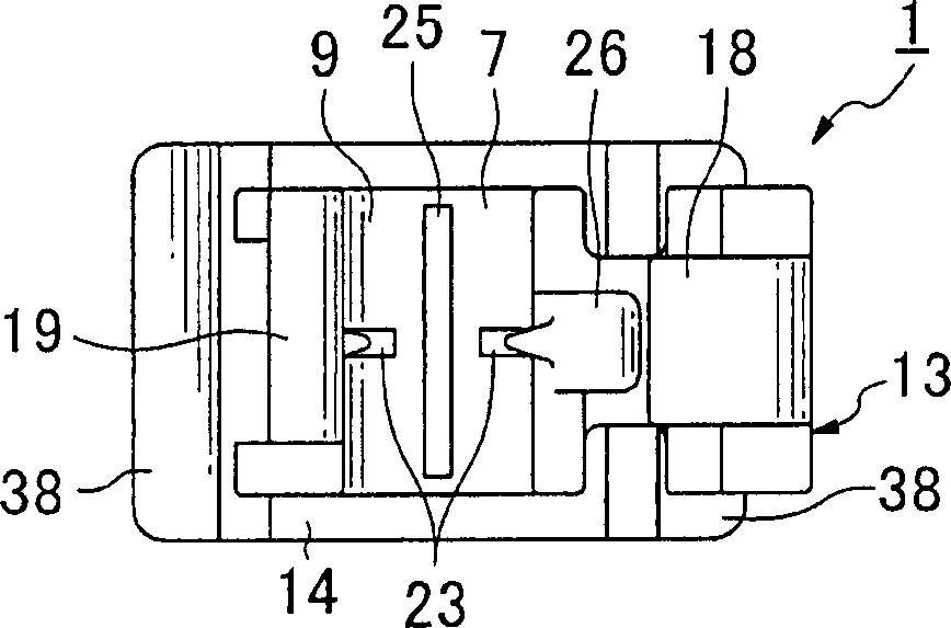
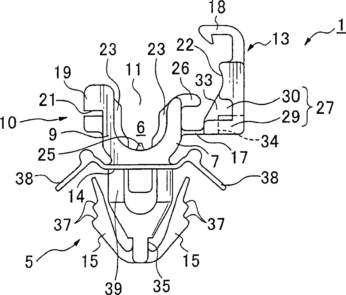
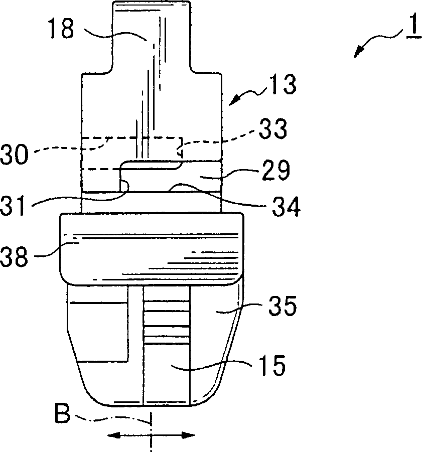
[0022] The cable clip of the present invention for connecting an elongated object to a bracket will be described below with reference to the accompanying drawings. The term "elongated article" herein generally includes various elongated objects such as, but not limited to, cables, wires, pipes or conduits, all such elongated objects are considered to be within the scope of the present invention.

[0023] The cable clamp 1 is moulded in plastic as a whole. like Figures 1 to 4 As shown, the cable clip 1 includes a fixing part 5, which is attached to a body panel 3 ( Figure 8 or Figure 9 ), a U-shaped clip part 10 comprising two clip arms 7, 9 raised from the fixed part 5 for holding the elongated object 2 ( Figure 5 ), and a cover 13 for closing the opening 11 in the clip portion 10. When an elongated object is held by the holding part 6 of the clip part 10 and the opening 11 is closed by the cover 13 , the elongated object 2 is held by the clip part 10 . like figure 1...


PUM


Abstract

The invention discloses a plastic cable clamp (1), which has a substantially U-shaped clamp part provided with a pair of clamp arms, and a cover (13) for closing the opening of the clamp part. The cover is pivotable about a hinge to close the opening of the clip portion and is held in the closed position by an engaging portion (18). A protrusion (26) is formed at one end of the hinged clamp arm, and a cutout portion (27) is formed in the cover to receive the protrusion. The cutout portion includes a first hole (29) extending from one side of the cover to the other side of the cover, and a second hole (30) adjacent to the first hole extending from the other side of the cover to one side of the cover. One wall (31) of the cutout portion is formed by the end surface of the first hole on the other side, and the other wall (33) is formed by the end surface of the second hole on one side.

Description

technical field [0001] The present invention relates to a clip for elongated objects, and in particular to a clip for elongated objects, such as a cable like a signal cable in an anti-lock braking system (ABS), which is mounted on a For example, on the brackets of the body panels. In particular, the present invention relates to a plastic clip which can be moulded in a simple forming mould using two detachable moulds and does not require additional punching elements such as sliders. For convenience of description, the clips of the present invention are generally referred to as "cable clips". [0002] This application claims priority from Japanese Application No. 2003-345747, filed on October 3, 2003, which is incorporated herein by reference. Background technique [0003] A cable clip with a cover, by which an elongated object is secured to a bracket such as a body panel, is well known in the art. For example, Japanese Appearance Patent No. 595528 (Patent Document 1) discl...

Claims


Application Information

Patent Timeline
Patent Type & Authority Applications(China)
IPC IPC(8): B60R16/02F16L3/10H02G3/30H02G3/38
CPCB60R16/0215F16L3/1025F16L3/1075H02G3/30H02G3/32
Inventor 河合康博平井贵之
Owner NEWFREY
Why Eureka
Try Eureka