Camshaft adjuster comprising a locking mechanism

A camshaft adjuster and locking device technology, which is applied to valve devices, machines/engines, mechanical equipment, etc., can solve the problem that the control time does not match the specified value, the unstable position of the camshaft adjuster, the increase of wear, and the inability to provide hydraulic medium. enough pressure

Active Publication Date: 2009-01-07
SCHAEFFLER TECH AG & CO KG
View PDF5 Cites 4 Cited by
  • Summary
  • Abstract
  • Description
  • Claims
  • Application Information

AI Technical Summary

Problems solved by technology

However, it turns out that the internal combustion engine does not provide sufficient pressure of the hydraulic medium when starting
The consequence of this is that the control time does not correspond to the specified value or an unstable position of the camshaft adjuster occurs, resulting in an "unstable" control time
In addition, undesired vibrations occur, which, in addition to increased wear, lead to undesired noise formation

Method used


Image

  • Camshaft adjuster comprising a locking mechanism

Examples


Embodiment Construction

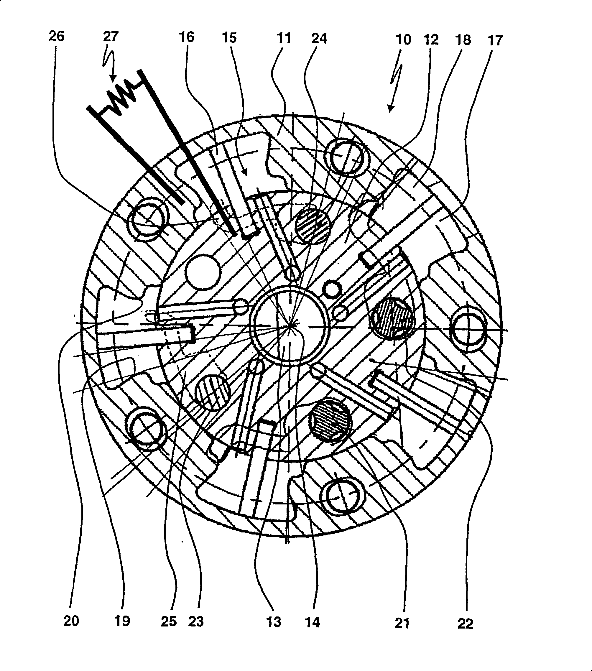
[0028] figure 1 A camshaft adjuster 10 for an internal combustion engine is shown, in which during the adjustment movement of the camshaft adjuster 10, the transmission member 11 can be twisted with respect to the driven member 12 around a rotating shaft 14 oriented perpendicular to the plane of the drawing, The transmission part is connected to the sprocket in a torsion-proof connection and is driven by a control chain, for example, the driven part is connected to the camshaft 13 in a torsion-proof connection, for example. The transmission part 11 is formed with working chambers 15 (here, five), which are restricted by the transmission part 11 radially outward and in two circumferential directions and restricted by the outer shell surface of the driven part 12 radially inward. The blade 16 of the transmission member 11 divides the working chamber 15 into the chamber 17 and the chamber 18. With the aid of the former, the camshaft adjuster 10 is adjusted in the direction of the en...


PUM


Abstract

The invention relates to a camshaft adjuster (10) for an internal combustion engine, comprising a locking mechanism. At least one locking element (21, 22) which can be locked in the zone of a central position (20) as well as at least one additional locking element (23, 24) that can be locked in the zone of a late final position (19) or an early final position (20) are provided such that the internal combustion engine can be selectively started from the final position (19, 20) or the central position.

Description

Technical field [0001] The invention relates to a camshaft adjuster for an internal combustion engine, which has a locking device in particular according to the preamble of claims 1 and 3. Background technique [0002] On the well-known hydraulically acting camshaft adjuster, the allocated control time of the internal combustion engine is adjusted by influencing the hydraulic ratio in the oppositely acting control room. These control rooms are adjusted on the "advanced control time" and "lagging control time". The role of the direction. If the internal combustion engine provides sufficient hydraulic pressure, so that sufficient hydraulic medium is injected into these chambers, the operation of this camshaft adjuster is not a problem. However, the situation shows that the internal combustion engine cannot provide sufficient pressure of the hydraulic medium when it is started. The consequence of this situation is that the control time does not match the specified value or an unstab...

Claims


Application Information

Patent Timeline
Patent Type & Authority Applications(China)
IPC IPC(8): F01L1/344
CPCF01L1/3442F01L1/34F01L2001/34483F01L1/344
Inventor 安德烈亚斯·施特劳斯
Owner SCHAEFFLER TECH AG & CO KG
Why Eureka
Try Eureka