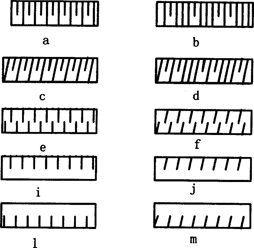
Interrupted tooth on edge of coin and souvenir badge and its printing method
A technology of commemorative medals and production methods, applied in coins, medals, badges, etc., to achieve the effect of ensuring production efficiency
- Summary
- Abstract
- Description
- Claims
- Application Information
AI Technical Summary
Problems solved by technology
Method used
Image
Examples
example 1
[0028] Example 1: The jig and equipment used in the above method of processing the half-tooth die sleeve are: the jig refers to a circular steel plate used to fix the die sleeve, see Figure 7 . There is a circular hole in the middle of the steel plate, the diameter of which is larger than the diameter of the wire teeth to be processed in the die sleeve. The other two small holes on the steel plate are used to pass through bolts to fix the die sleeve, and the positions of the holes are consistent with the positions of the bolt holes on the die sleeve blank. The equipment refers to the wire cutting machine tool. There are upper and lower sets of wire guide nozzles on the wire cutting machine. When processing straight wire teeth, the projections of the connection lines of the upper and lower guide wire sleeves on the horizontal plane are coincident. See Figure 8 . During the processing, the upper and lower guide wire nozzles cut and process the mold sleeve according to the p...
example 2
[0055] Example 2: There are basically two types of demoulding jig structures for oblique wire teeth printed on the side of coins: one is the B structure, and the mold sleeve 8 is fixed, and the lower ejector rod 2 is pushed up in a spiral motion. Push the product out when done. The feature of the fixture B structure is: spiral grooves are processed on the round lower mandrel 2, see Figure 14 , the direction of rotation of the spiral groove is the same as the direction of rotation of the upper thread teeth of the product. For example, the direction of rotation of the inclined wire teeth on the edge of the product is to the right, so the direction of rotation of the spiral groove on the lower ejector rod is also to the right. When the lower ejector rod 2 moves upward, because there is a limit rod 4 fixed on the equipment in the spiral groove, the lower ejector rod 2 can only rotate and rise along the chute; see Figure 15 . The other is the A structure, see Figure 16 . In ...
PUM
 Abstract
Description
Claims
Application Information
 - R&D
- Intellectual Property
- Life Sciences
- Materials
- Tech Scout
- Unparalleled Data Quality
- Higher Quality Content
- 60% Fewer Hallucinations
Browse by: Latest US Patents, China's latest patents, Technical Efficacy Thesaurus, Application Domain, Technology Topic, Popular Technical Reports.
© 2025 PatSnap. All rights reserved.Legal|Privacy policy|Modern Slavery Act Transparency Statement|Sitemap|About US| Contact US: help@patsnap.com


