

Support method for unlatching dormer window
A support method and skylight technology, applied in the direction of skylight/dome, wing opener, door/window accessories, etc., can solve the problem that the open position of the casement cannot be positioned at will, and achieve the effect of convenient use
Inactive Publication Date: 2005-06-29
杭州高盾科技有限公司
View PDF0 Cites 8 Cited by
- Summary
- Abstract
- Description
- Claims
- Application Information
AI Technical Summary
Problems solved by technology
[0003] In order to overcome the problem that the opening position of the casement cannot be positioned arbitrarily in the existing top-hung skylight, the invention provides a support method that can be positioned arbitrarily when the sash is opened
Method used
View moreImage
Smart ImageViewing Examples

Examples
Embodiment Construction
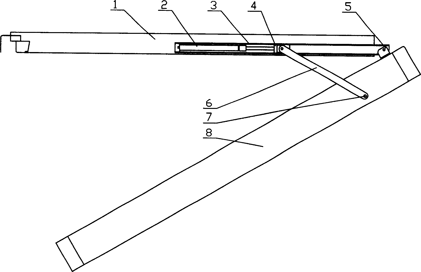
[0009] Fig. 1 is the state when casement is opened, and sash (1) and track (3) are installed together, and hinge seat (5) is installed on the top of window frame (8), and track (3) pin and hinge seat (5) ) connection, the friction slider (4) is installed in the track (3), and can slide in the track (3), one end of the support rod (6) is connected with the window frame (8) by a pin shaft (7), and the other end Also connect with pin shaft and friction slide block (4), and one end of thrust spring (2) is connected with friction slide block (4), and the other end is connected with track (3), selects the power of suitable thrust spring (2) for use, just The casement (1) can be positioned arbitrarily when it is opened.
Login to View More PUM
 Abstract
The invention relates to a support method for an openable skylight, which is mainly suitable for top-hung skylights, the window sash (1) and the track (3) are installed together, the hinge seat (5) is installed on the upper part of the window frame (8), and the track ( 3) Connect the hinge seat (5) with a pin shaft, the friction slider (4) is installed in the track (3), and can slide in the track (3), and one end of the support rod (6) is connected with a pin shaft (7) It is connected with the window frame (8), and the other end is also connected with the friction slider (4) with a pin shaft, and one end of the spring (2) is connected with the friction slider (4), and the other end is connected with the track (3). The power of the spring (2) can make the casement (1) be positioned arbitrarily when it is opened, which is convenient to use.
Description
Technical field [0001] The invention relates to a supporting method for an openable skylight, which is mainly applicable to a top-hung skylight. Background technique [0002] At present, the used top-hung skylights are all supported by gas springs when they are opened, that is, one end of the gas spring is mounted on the window frame, the other end is mounted on the window casement, and a gas spring is installed on each side of the window frame. Only the gas spring, when the sunroof is opened, the force of the gas spring is used to push the sash open. This top-hung skylight has a simple structure, but because the force of the gas spring is relatively constant, the opening position of the casement cannot be positioned arbitrarily, and often can only be at the maximum opening position. Contents of the invention [0003] In order to overcome the problem that the open position of the casement cannot be positioned arbitrarily in the existing top-hung skylight, the invention pr...
Claims
Login to View More Application Information
Patent Timeline
 IPC IPC(8): E04D13/03E05F1/10E05F3/16
Inventor胡东英
Owner杭州高盾科技有限公司