Knitting machine

A technology of knitting machine and frame, applied in the directions of knitting, weft knitting, warp knitting, etc., can solve the problems of cumbersome manufacturing and installation, etc.

Inactive Publication Date: 2014-08-20
KARL MAYER TEXTILMASCHFAB GMBH
View PDF8 Cites 0 Cited by
  • Summary
  • Abstract
  • Description
  • Claims
  • Application Information

AI Technical Summary

Problems solved by technology

These supporting mechanisms must be maintained, such as lubricated, and due to their high precision, they are relatively cumbersome to manufacture and install

Method used


Image

  • Knitting machine
  • Knitting machine
  • Knitting machine

Examples


Embodiment Construction

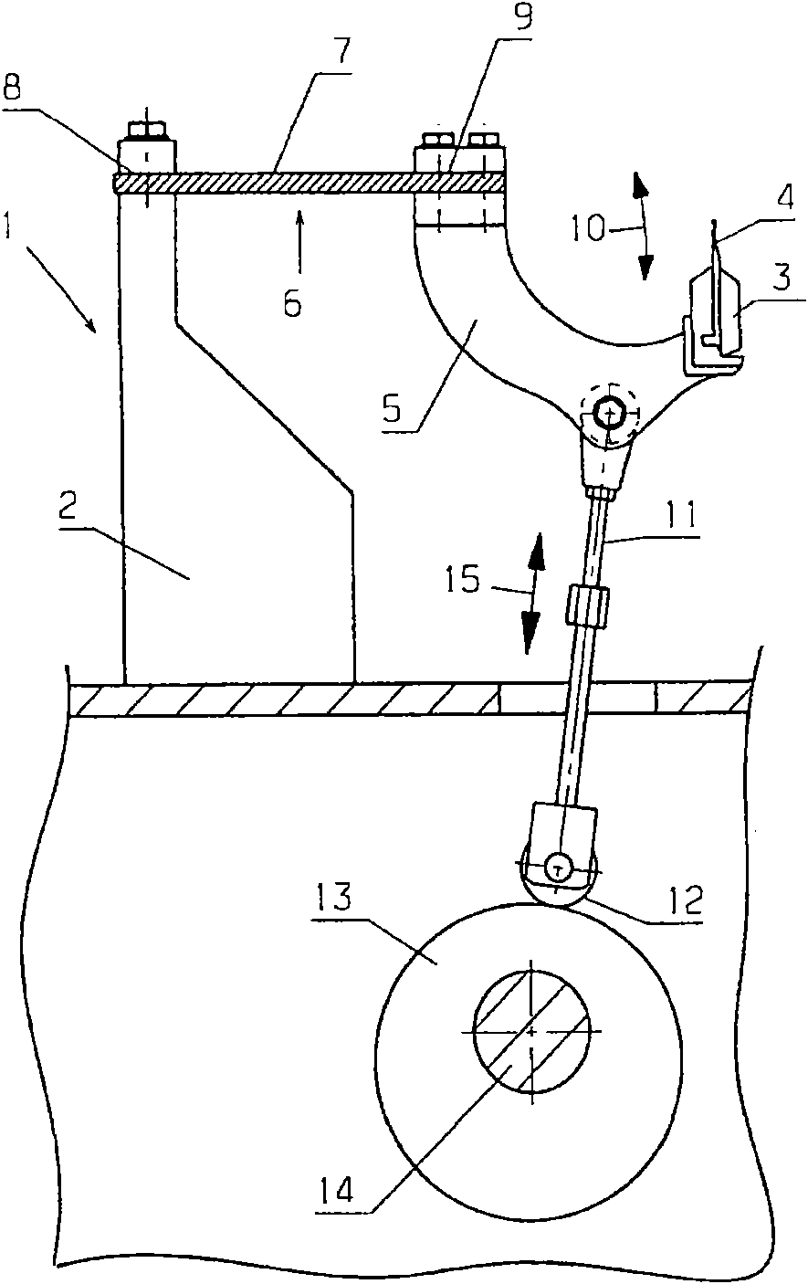
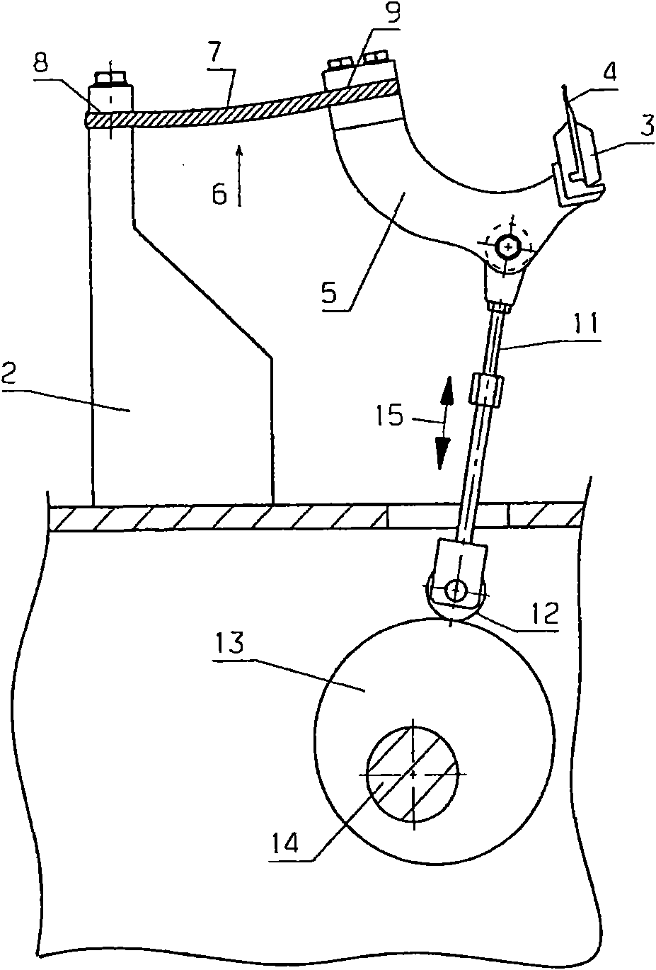
[0021] figure 1 A schematic partial sectional view of a knitting machine 1 with a frame 2 and a loop forming tool bar 3, in the present case a needle bar with needles 4, these The knitting needles are arranged one after the other perpendicular to the drawing surface.

[0022] For the sake of clarity, the other bars of the knitting machine 1 are not shown, but are of course present in practice.

[0023] The looping tool bar 3 is fixed on the front end of the support rod 5 . The support rod is connected with the frame 2 through a bending joint device 6 .

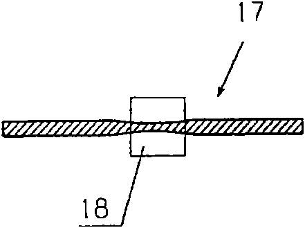
[0024] In the present case, the bending joint has a leaf spring 7 made of fiber-reinforced plastic. The leaf springs are connected to the frame 2 via a momentary fastening (momentenfest) connection 8 . Furthermore, the leaf spring 7 is connected to the support rod 5 by means of an instantaneously fixed connection mechanism 9 . Immediately fixed connecting mechanism 8,9 makes looping tool bar 3 swing as shown by double arr...


PUM


Abstract

The knitting machine (1) has a machine frame (2), where a knitting tool bar (3) is pivotable by a pivot drive relative to the machine frame. The knitting tool bar is connected to the machine frame via a flexural joint arrangement (6). The flexural joint arrangement has multiple bending joints distributed over the length of the knitting tool bar, where the bending joints have flat springs made of fiber reinforced plastic.

Description

technical field [0001] The invention relates to a knitting machine with a frame and at least one loop forming tool bar, which can be swiveled relative to the frame by means of a pivot drive. Background technique [0002] In the case of a knitting machine, in order to form a loop, the loop forming tool must be relatively moved. The same kind of loop forming tool is fixed on the loop forming tool bar here. In order to realize the movement of the looping tool, the looping tool bar is pivoted several times relative to the machine frame. This applies, for example, to knitting needle bars, but also to bars with loop sinkers (Polplatine), or to bars with sliders (Schieberplatine). The bar with the guide needles must also be pivoted relative to the frame. Here, however, a traversing movement also takes place, so that the guide needle can, for example, perform a closed circular movement around the knitting needle. [0003] A knitting machine of the type mentioned at the outset is...

Claims


Application Information

Patent Timeline
Patent Type & Authority Patents(China)
IPC IPC(8): D04B27/24D04B15/00
CPCD04B27/08
Inventor O·弗兰克C·博切克
Owner KARL MAYER TEXTILMASCHFAB GMBH
Why Eureka
Try Eureka