Lamp crimping and assembling mechanism

A technology of assembly mechanism and lamps, which is applied in the direction of manufacturing tools, metal processing, metal processing equipment, etc., can solve the problems of inaccurate positioning, long upward stroke of the upper pressing component, damage of two parts, etc., so as to avoid inconvenient operation and improve production The effect of improving safety and productivity

Active Publication Date: 2010-11-17
CHANGZHOU XINGYU AUTOMOTIVE LIGHTING SYST
View PDF3 Cites 22 Cited by
  • Summary
  • Abstract
  • Description
  • Claims
  • Application Information

AI Technical Summary

Problems solved by technology

The crimping assembly mechanism of this structure is to put the two parts together first, and then move to the pressing assembly, and the position of the two parts placed is different from the crimping assembly operation position, so the function of moving the parts to the press In the process of moving, the relative position of the two parts will change, which will cause the position of the two parts to be wrong after assembly, resulting in the unreliable connection of the two parts.
In addition, because the parts are placed manually, the positioning of the two parts is not accurate, which can easily cause damage to the two parts. The operation is laborious, the assembly efficiency is low, and the upper surface of the lamp is easily scratched.
In order to take out the zero assembly after crimping and assembly, the upper pressing assembly needs to have a long upward stroke, which further reduces the assembly efficiency of parts crimping

Method used


Image

  • Lamp crimping and assembling mechanism
  • Lamp crimping and assembling mechanism
  • Lamp crimping and assembling mechanism

Examples


Embodiment Construction

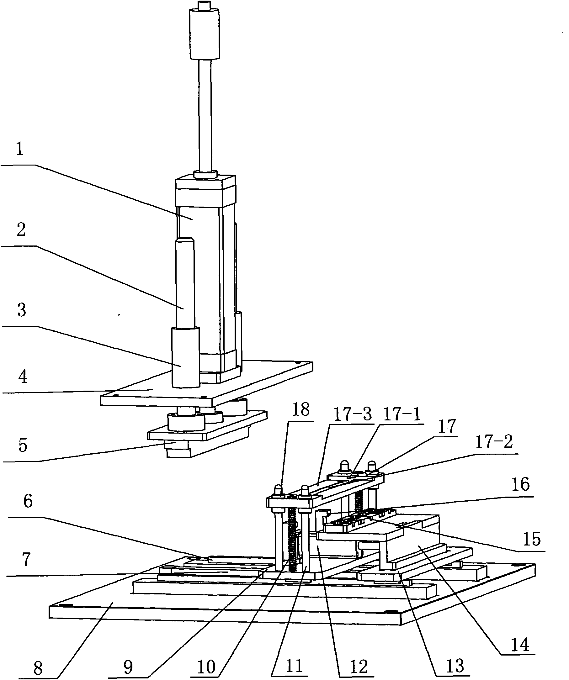
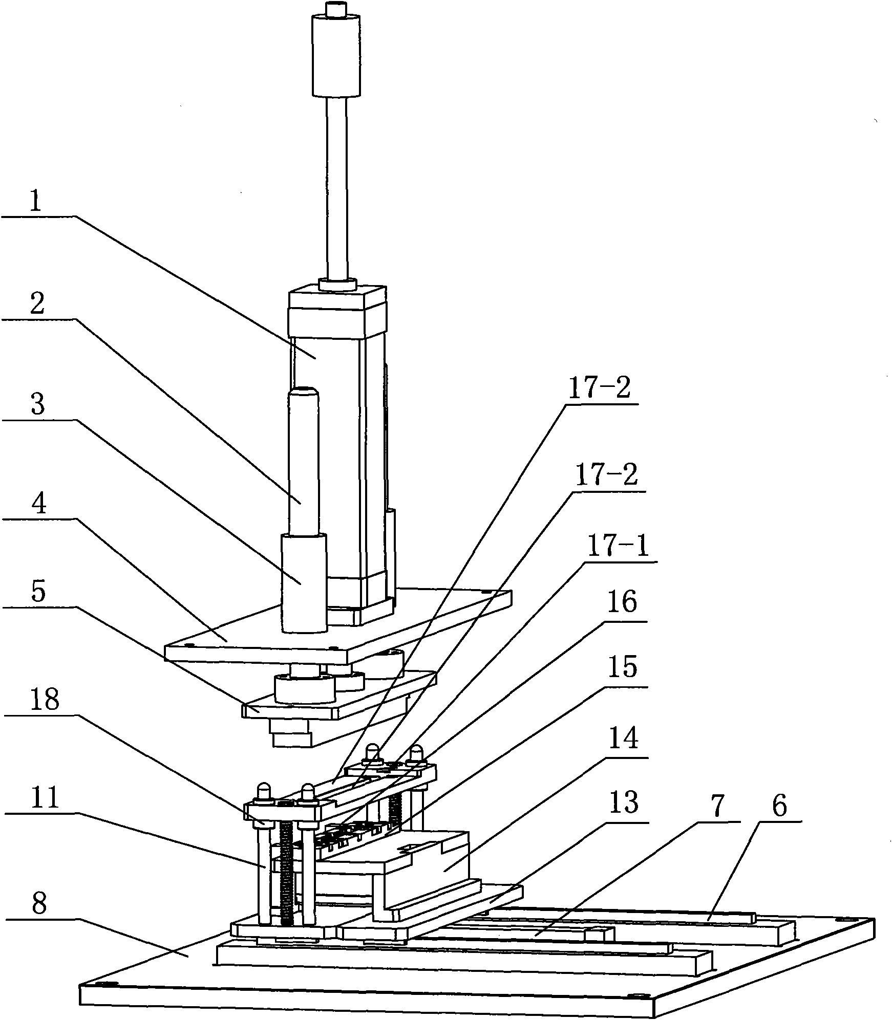
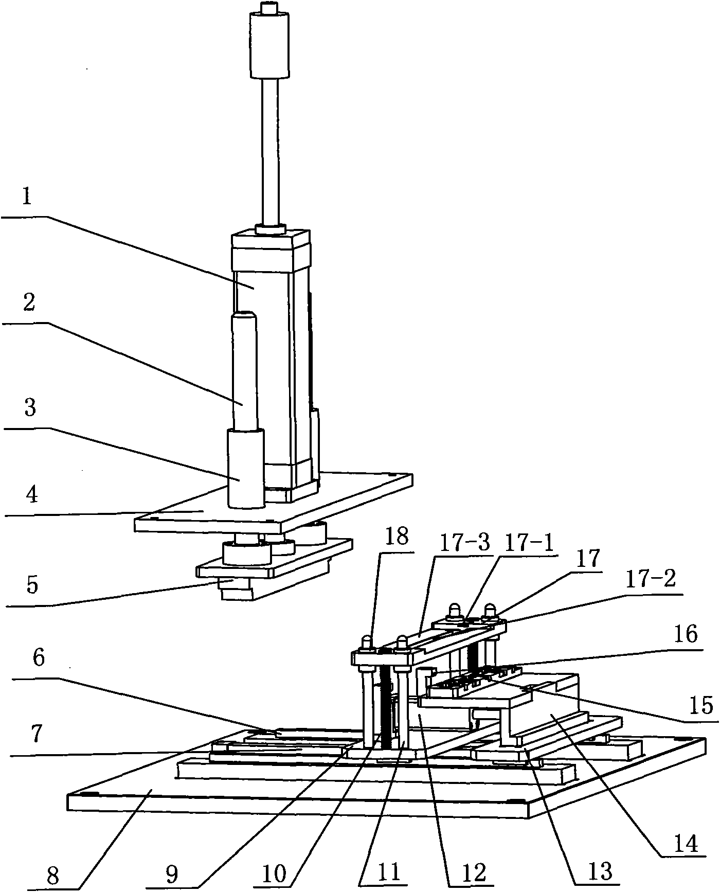
[0011] See figure 1 , 2 As shown, the lamp crimping assembly mechanism of the present invention includes an upper pressing assembly and a lower pressing assembly, and the upper pressing assembly includes an upper connecting seat 4, an upper cylinder 1 installed on the upper connecting seat 4, an upper guide sleeve 3 and an upper pressing assembly. block 5, the piston of the upper cylinder 1 is connected to the upper pressure block 5, and more than two upper guide posts 2 connected to the upper pressure block 5 are respectively arranged in the two upper guide sleeves 3, and pass through under the action of the upper cylinder 1 The piston drives the upper pressing block 5 to move up and down, and the upper guide sleeve 3 moves up and down along the upper guide post 2, so as to reduce the displacement of the upper pressing block 5 and ensure the accuracy of crimping assembly. See figure 1 , 2 As shown, the pressing assembly of the present invention includes a lower connection ...


PUM


Abstract

The invention relates to a lamp crimping and assembling mechanism, which comprises an upper crimping assembly and a lower crimping assembly, wherein a lower connecting base of the lower crimping assembly is provided with two linear guide tracks and a first cylinder in the transverse direction; a first sliding plate and a second sliding plate are arranged on the two linear guide tracks and are movable; the piston of the first cylinder is connected with the first sliding plate; at least two springs arranged on the first sliding plate are supported to a first limiting plate; the first limiting plate is provided with a mounting surface for mounting parts, a positioning groove and an H-shaped discharge notch arranged on the mounting surface; a second cylinder arranged on the first sliding plate is connected with a supporting plate arranged on the second sliding plate; a second limiting plate is arranged on the supporting plate; the second limiting plate is provided with a mounting surface for mounting parts and more than two spacing grooves; and the first sliding plate is provided with a positioning block for height positioning of the second limiting plate, and the positioning block is provided with a side positioning notch. The lamp crimping and assembling mechanism ensures that two parts can be placed in a staggered mode, can improve the assembly efficiency, and has accurate positioning, and safe and convenient operation.

Description

technical field [0001] The invention relates to a lamp crimping assembly mechanism, which belongs to the technical field of lamp manufacturing. Background technique [0002] At present, in the manufacture of automobile lamps, it is often necessary to carry out vertical crimping assembly of two parts, such as the connection between the lamp housing of the high-mounted brake lamp and the circuit board. The crimping assembly mechanism generally uses an upper pressure component and a lower pressure component. During operation, first place the two parts that need to be matched along the installation position, and then put the two parts that have been placed into the lower pressure component for use. on the positioned mounting block, and then start the crimping machine, and press and assemble the parts by pressing the upper pressing component on the lower pressing component. The crimping assembly mechanism of this structure is to put the two parts together first, and then move to...

Claims


Application Information

Patent Timeline
Patent Type & Authority Applications(China)
IPC IPC(8): B23P19/027
Inventor 叶红星孙书强刘秋鹏
Owner CHANGZHOU XINGYU AUTOMOTIVE LIGHTING SYST
Why Eureka
Try Eureka