
Applying device and pressure-relief cavity and applying method used by it

A technology of coating device and decompression chamber, which is applied in the direction of the device and coating of liquid coating on the surface, to achieve the effect of suppressing step unevenness and high decompression efficiency

Inactive Publication Date: 2005-08-24
LINTEC CORP
View PDF1 Cites 0 Cited by
  • Summary
  • Abstract
  • Description
  • Claims
  • Application Information

AI Technical Summary

Problems solved by technology

[0006] The object of the present invention is to provide a coating device, a decompression chamber and a coating method, in the coating device, a decompression chamber and a coating method, aiming at forming a liquid coating layer on a continuously walking sheet Coating steps, suppress coating defects such as step unevenness, coating ribs, air bubbles, etc., provide a good quality coating surface, and high decompression efficiency

Method used


Image

  • Applying device and pressure-relief cavity and applying method used by it
  • Applying device and pressure-relief cavity and applying method used by it
  • Applying device and pressure-relief cavity and applying method used by it

Examples


Embodiment 2

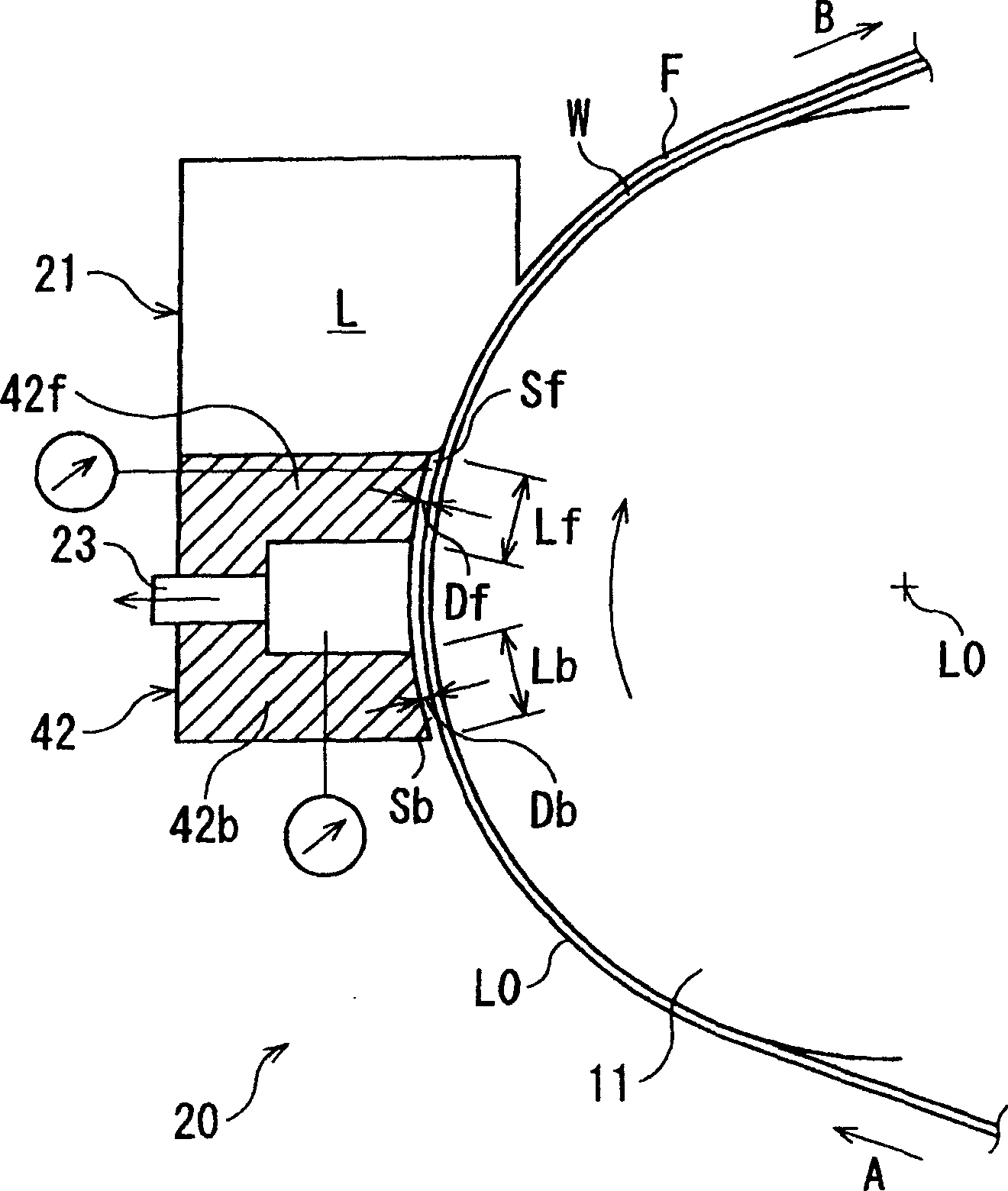
[0085] In Example 2,

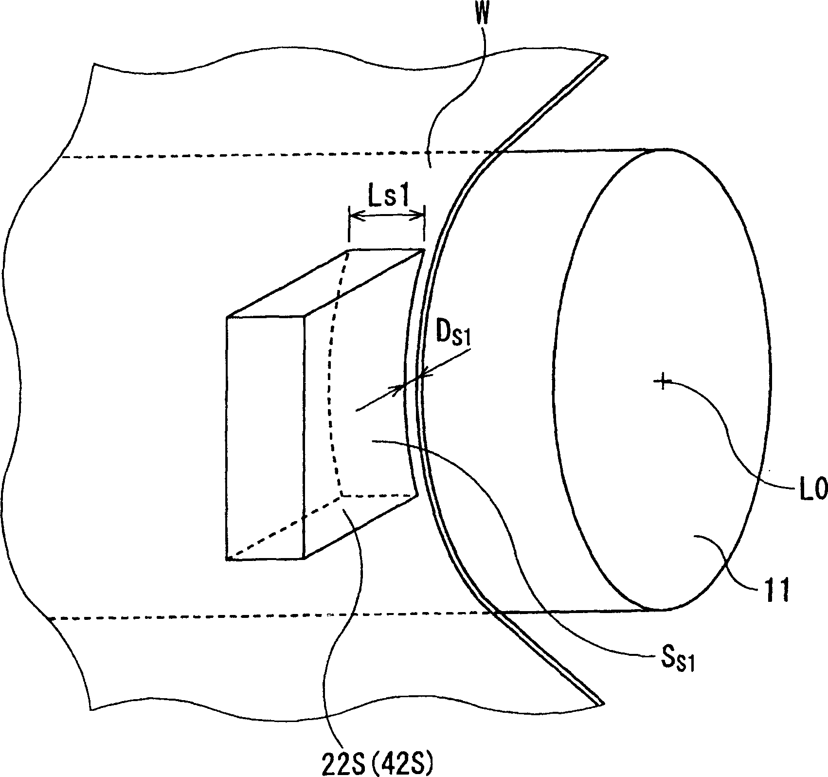
[0086] Db=Ds 1 =Df=500μm

[0087] Lb=Ls 1 =Lf=5mm

[0088] According to the above conditions, the critical coating speed of Comparative Example 1 (the maximum coating speed without air concomitant motion) is 80m / min. On the contrary, the critical coating speed of Example 1 rises to 110m / min. In the case of Example 2, the above coating speed was increased to 120 m / min.

example 4

[0100] In instance 4

[0101] Db=Ds 1 =Df=500μm

[0102] Lb=Ls 1 =Lf=50mm

[0103] According to the above conditions, in the case of Comparative Example 2, the rate of change of the degree of decompression near the coating strip (equal to the rate of change of the degree of decompression in the decompression chamber) was 8%, and the critical coating speed was 150 m / min. , In contrast, in the case of Example 3, the rate of change of the decompression degree near the coating strip (equal to the rate of change of the decompression degree in the decompression chamber) is reduced by 5%, and the critical coating speed is increased to 180m / min .

[0104] On the other hand, in the case of Example 4, the rate of change in the degree of reduced pressure in the decompression chamber was 5%, and the rate of change in the degree of reduced pressure in the vicinity of the coated lath was reduced to 3%. In addition, the critical coating speed was raised to 200 m / min.

[0105]As mention...


PUM


Abstract

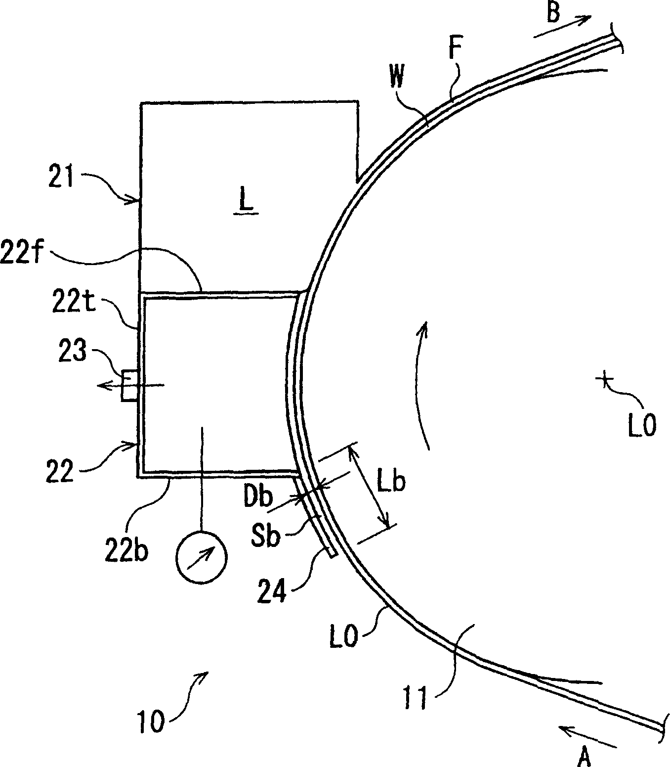
To suppress occurrence of a defective coating film layer without lowering a decompression efficiency in a coating apparatus for forming a coating film layer on a continuously traveling web. The web W is tightened on a backing roll 11. A coating head 21 is arranged in a shoulder portion of the web W-supported backing roll 11 and a decompression chamber 22 is arranged on the upper stream side of the coating head. A guide plate 24 abutting on the web W is arranged on a back plate 22b of the decompression chamber 22 on the upper stream side. When a gap between the guide plate 24 and the surface of the web W is defined as Db, the length Lb of the guide plate 24 along the traveling direction of the web is set to be equal to or longer than twenty times of the gap Db.

Description

technical field [0001] The present invention relates to a coating device for coating a coating liquid on a continuously running strip-shaped sheet such as paper, cloth, or plastic film. Background technique [0002] In recent years, along with the improvement of the performance and function of coated products, the demand for the film thickness accuracy of the coating layer has increased. However, in the coating device for coating the coating liquid on the continuously running strip-shaped sheet, due to various reasons in the coating step, step-like unevenness (non-uniform coating film thickness along the longitudinal direction of the sheet) occurs. Phenomenon), coating defects such as coating ribs, bubbles, etc. In order to suppress the phenomenon of accompanying air (a phenomenon in which a part of the accompanying air layer near the sheet is mixed between the coating liquid and the sheet), which is one of the causes of these coating defects, in the slot die coater, the sl...

Claims


Application Information

Patent Timeline
Patent Type & Authority Applications(China)
IPC IPC(8): B05D7/00B05C3/132B05C3/18B05C5/02B05C11/10
Inventor 朱峰承兴宫泽靖直渡边学町田隆
Owner LINTEC CORP
Learn More