
Intake arrangement

A technology of air intake device and air intake channel, which is applied in the direction of fuel air intake, charging system, combustion air/combustion-air treatment, etc. Deterioration of engine exhaust emissions, etc.

Active Publication Date: 2005-08-31
ANDREAS STIHL AG & CO KG
View PDF1 Cites 7 Cited by
  • Summary
  • Abstract
  • Description
  • Claims
  • Application Information

AI Technical Summary

Problems solved by technology

When the air intake device swings, especially when the hand-held tool swings, the fuel attached to the wall of the air intake will suddenly fall off the wall of the air intake, thereby adding a large amount of fuel to the two-stroke engine again, resulting in two Unstable operation of stroke engines and deterioration of exhaust emission values ​​of two-stroke engines

Method used


Image

  • Intake arrangement
  • Intake arrangement
  • Intake arrangement

Examples


Embodiment Construction

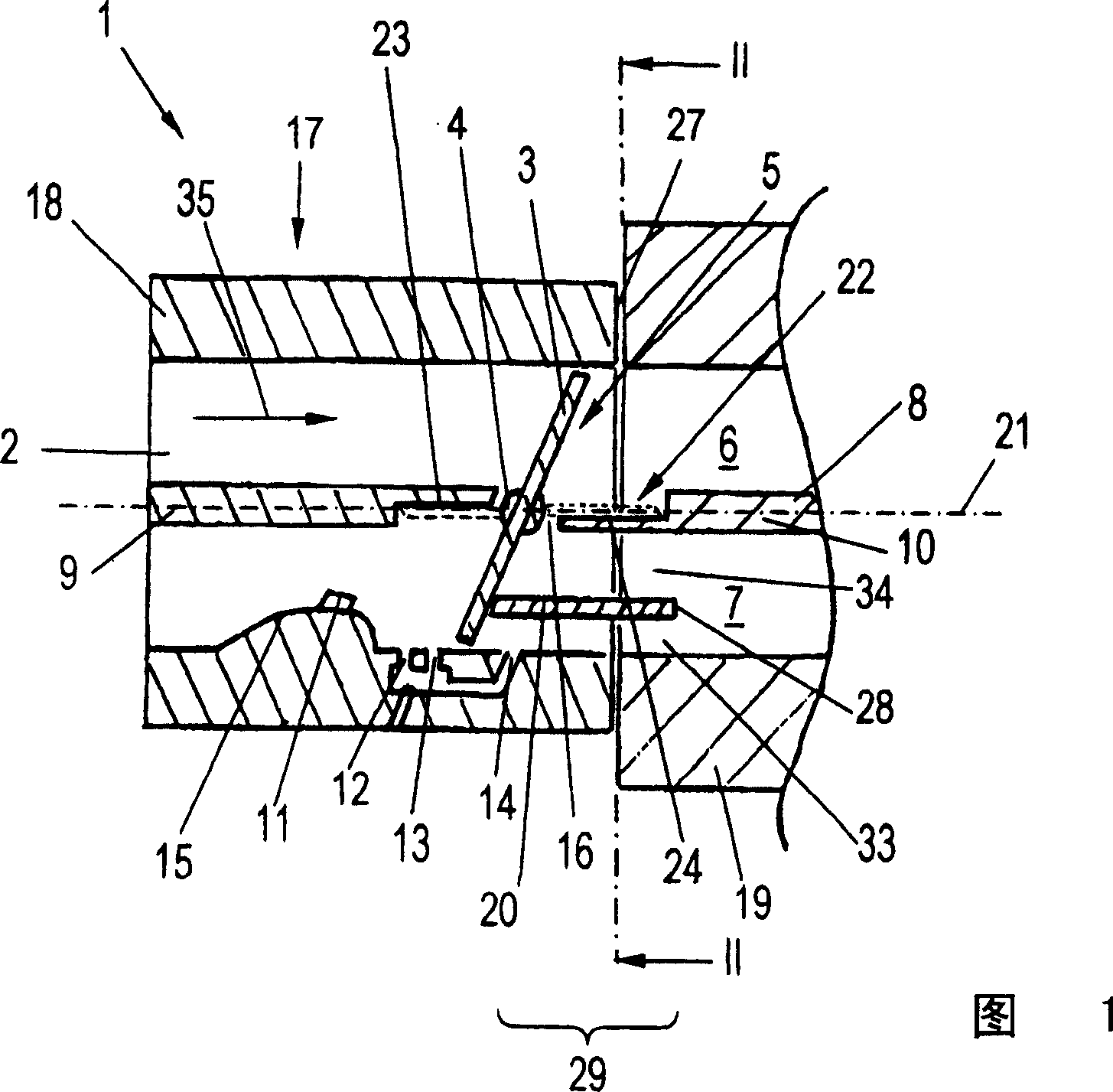
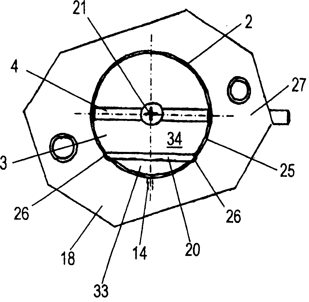
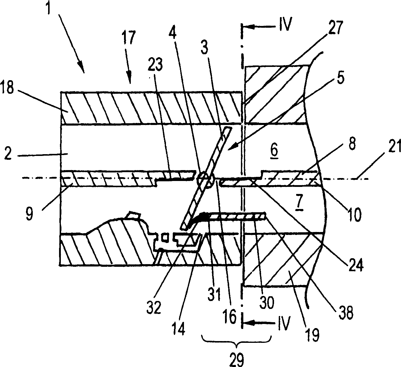
[0014] FIG. 1 shows an air intake device 1 for introducing combustion air into a two-stroke engine, in particular for a hand-held tool, such as a chainsaw, free-cut cutter or the like. The intake device 1 has an intake duct 2 , in which a throttle valve 3 is mounted pivotably by means of a throttle shaft 4 , wherein the throttle valve 3 is arranged in a carburetor 17 . An air filter, which is not shown in FIG. 1 , can be installed upstream of the carburetor 17 in the direction of flow 35 . A flange 19 is arranged downstream of the carburetor 17 , which can be, for example, a flange of a two-stroke engine. However, it can also be an intermediate flange. The partition wall 8 divides the intake channel 2 into an air channel 6 and a mixture channel 7 . In this case, the partition wall section 9 is upstream of the throttle valve 3 and the partition wall section 10 is downstream of the throttle valve 3 . Advantageously, the partition wall 8 extends over the entire length of the i...


PUM


Abstract

An intake arrangement ( 1 ) for a two-stroke engine includes an intake channel ( 2 ) in which a throttle flap ( 3 ) is pivotally journalled with a throttle shaft ( 4 ). Downstream of the throttle flap ( 3 ), a partition wall ( 8 ) is mounted on the intake channel ( 2 ) and this partition wall partitions the intake channel ( 2 ) into an air channel ( 6 ) and a mixture channel ( 7 ). In the idle position ( 5 ) of the throttle flap ( 3 ), at least one fuel opening ( 14 ) opens into the mixture channel ( 7 ) downstream of the throttle flap ( 3 ). A connecting opening ( 16 ) between the air channel ( 6 ) and the mixture channel ( 7 ) is provided between the partition wall ( 8 ) and the throttle shaft ( 4 ) in the idle position ( 5 ) of the throttle flap ( 3 ). A shield ( 20, 30 ) is mounted in the mixture channel ( 7 ) between the fuel opening ( 14 ) and the connecting opening ( 16 ) in order to achieve a good swing performance of the two-stroke engine. The shield reduces the passing of fuel into the air channel and therefore the degree of wetting of the air channel with fuel.

Description

technical field [0001] The present invention relates to an air intake device for a two-stroke engine, in particular for a hand-held tool, such as a chainsaw, a free cutter or a tool of the same type as specified in the preceding part of claim 1. device. Background technique [0002] An intake system for a two-stroke engine is known from DE 101 60 539 A1, the intake duct of which is divided by a partition wall downstream of the throttle valve into an air duct and a mixture duct. In the range of the throttle valve, there is a hole in the partition wall, which is closed when the throttle valve is at the full load position; when the throttle valve is at the idle position, the fuel can pass through the connection hole from the mixed air channel to the air channel, so that the air channel The walls are also wetted with fuel at idle. When the air intake device swings, especially when the hand-held tool swings, the fuel attached to the wall of the air intake will suddenly fall off...

Claims


Application Information

Patent Timeline
Patent Type & Authority Applications(China)
IPC IPC(8): F02B25/16F02B25/22F02B75/02F02D9/10F02M9/08F02M35/10F02M35/108
CPCY02T10/146F02M35/10255F02M35/10262F02M9/08F02M35/10196F02B25/22F02M35/108F02D9/1045F02B2075/025Y02T10/12
Inventor A·普拉格尔
Owner ANDREAS STIHL AG & CO KG
Learn More