Method for producing a woven belt strap

A technology of braided belts and restraint belts, which is applied in the weaving field of braided belts, and can solve problems such as discomfort and danger for vehicle occupants

Inactive Publication Date: 2005-08-31
BERGER & HLDG
View PDF2 Cites 14 Cited by
  • Summary
  • Abstract
  • Description
  • Claims
  • Application Information

AI Technical Summary

Problems solved by technology

When the belt is so deformed, it can no longer be neatly wound, and when used as a restraint belt for the veh

Method used


Image

  • Method for producing a woven belt strap
  • Method for producing a woven belt strap
  • Method for producing a woven belt strap

Examples


Embodiment Construction

[0015] The sequence of the method according to the invention is as follows, for example:

[0016] The first weft picking:

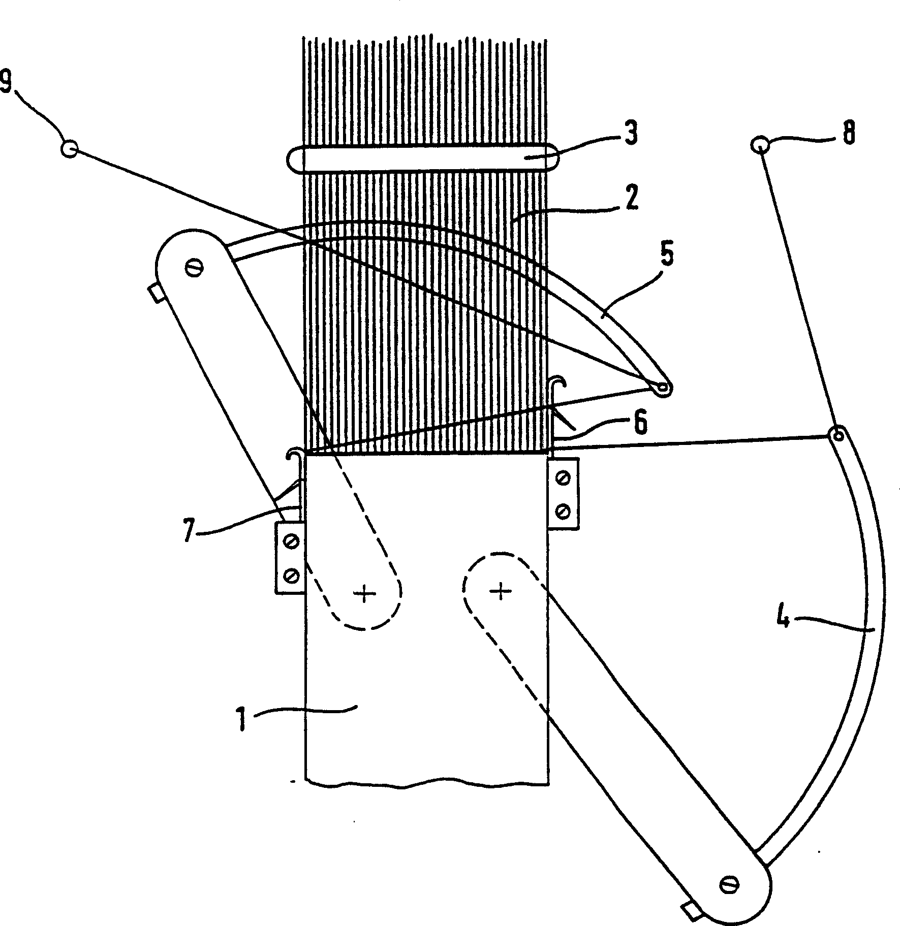
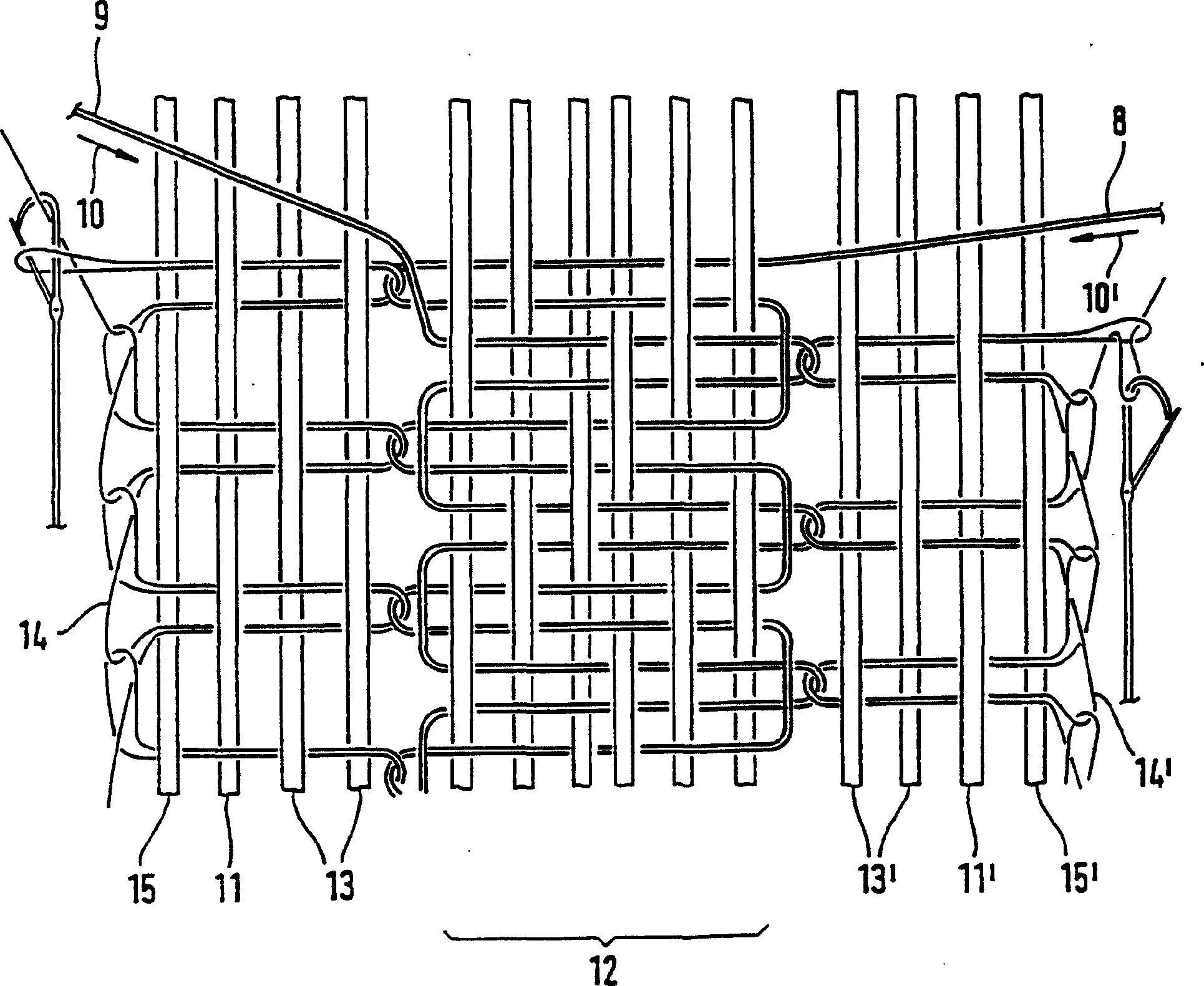
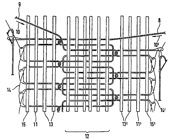
[0017] In the shed (shed) formed by the warp yarn 2, utilize the weft yarn needle 5 to drop a weft yarn 9 from left to right, and utilize the knitting needle 6 on the right side to make it meet the tuck thread (tuckthread) on the right side edge of the belt ( not shown) interspersed with each other (this particular case is just as described).

[0018] After the weft needle has returned to the left, the weft-inserted yarn is attached to the finished fabric 1 by means of the reed 3 .

[0019] During one revolution of the machine, the weft needle on the left and the knitting needle on the right remain stationary while changing the shed.

[0020] The second weft picking:

[0021] Utilize the right side weft yarn needle 4 to drop weft yarn 8 from the right side in the shed and utilize the left side knitting needle 7 to make it interweave with a tuck yarn. ...


PUM


Abstract

The invention relates to a method for producing a woven belt strap (1), particularly an automobile safety belt strap, which is characterized in that the weft threads (8, 9) are alternately inserted from one belt strap side and then from the other belt strap side, during which at least the first of both warp threads (11, 11', 15, 15') remain on the respective weft entry side without being woven, and a catch thread (14, 14'), which loops the weft on the weft exit side, is drawn into the weave until the warp threads, which remained unwoven with the preceding weft, are woven by the catch thread loop.

Description

technical field [0001] The invention relates to a weaving method for a braided belt, in particular to a restraint belt for vehicle occupants. Background technique [0002] In the manufacture of transverse rigid belts, in particular restraint belts for vehicle occupants on narrow knitting machines, it is known to use stiff weft yarns, especially monofilament yarns. This hard weft yarn is defective at the edge of the weave fold, which protrudes from the weave to form a hard jagged weave edge. [0003] Many attempts have been made to overcome the negative effects of such hard weft materials. [0004] From EP0021104A is known a double knitting needle technique which utilizes a knitted course on the exit side of the weft yarn to solve the above problem by forming rounded edges in weaving. [0005] DE3345508C2 discloses a double knitting needle technology with a knitting structure comprising a 2:2 edge on the exit side of the weft yarn. [0006] PCT / EP / 48285 discloses a single ...

Claims


Application Information

Patent Timeline
IPC IPC(8): B60R22/12D03D1/00D03D15/02D03D35/00D03D47/06D03D47/42D03D47/44
CPCD03D1/0005D03D47/06D03D35/00D03D47/44
Inventor 埃里希・赖特尔
Owner BERGER & HLDG
Why Eureka
Try Eureka