Electric motor for hand toolroom machines

A technology of electric motors and tools, applied in the field of electric motors, can solve the problems of troublesome and time-consuming removal of carbon brushes

Inactive Publication Date: 2005-08-31
SCINTILLA AKTIENGES
View PDF0 Cites 2 Cited by
  • Summary
  • Abstract
  • Description
  • Claims
  • Application Information

AI Technical Summary

Problems solved by technology

In this case, the detachment of the locking cap from the brush holder and the removal of the carbon brushes is cumbersome and time-consuming

Method used


Image

  • Electric motor for hand toolroom machines
  • Electric motor for hand toolroom machines
  • Electric motor for hand toolroom machines

Examples


Embodiment Construction

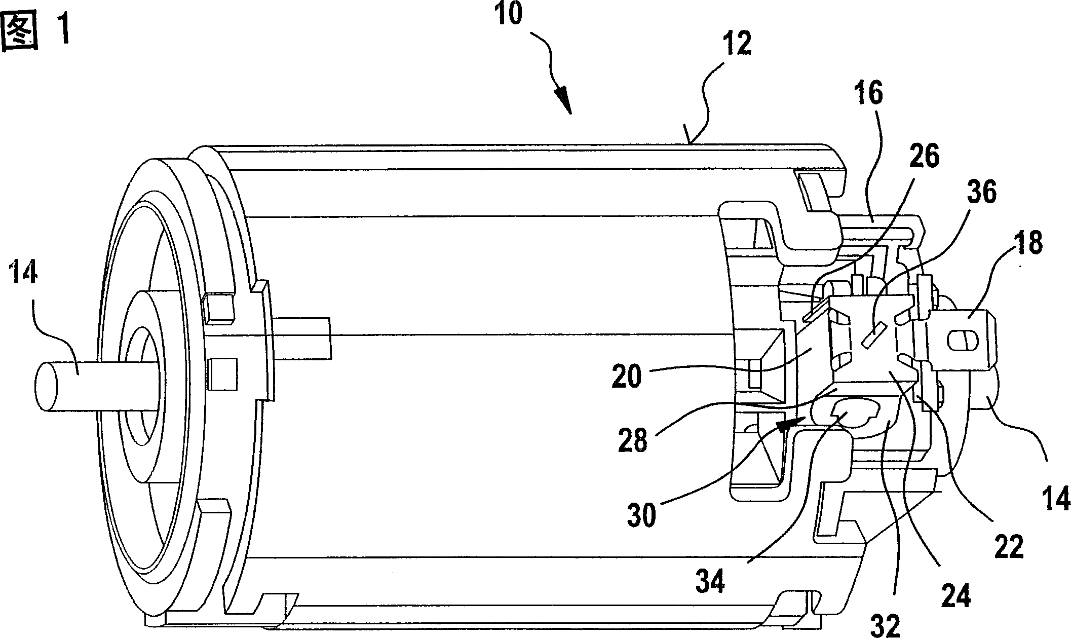
[0016] FIG. 1 shows an electric motor 10 having a housing 12 in the form of a cylindrical shell made of sheet metal with a rotor (not shown) inside and whose motor shaft 14 projects outwardly from the ends of the electric motor 10. out. On the right in the viewing direction, the electric motor 10 has a carbon brush plate 16 on the end side, which is flanged to the housing 12 . The carbon brush plate 16 is penetrated at its center by the other end of the motor shaft 14 .

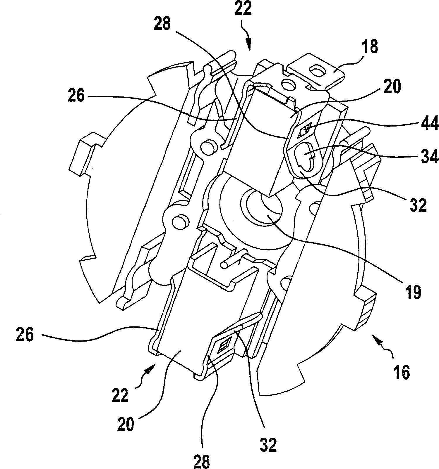
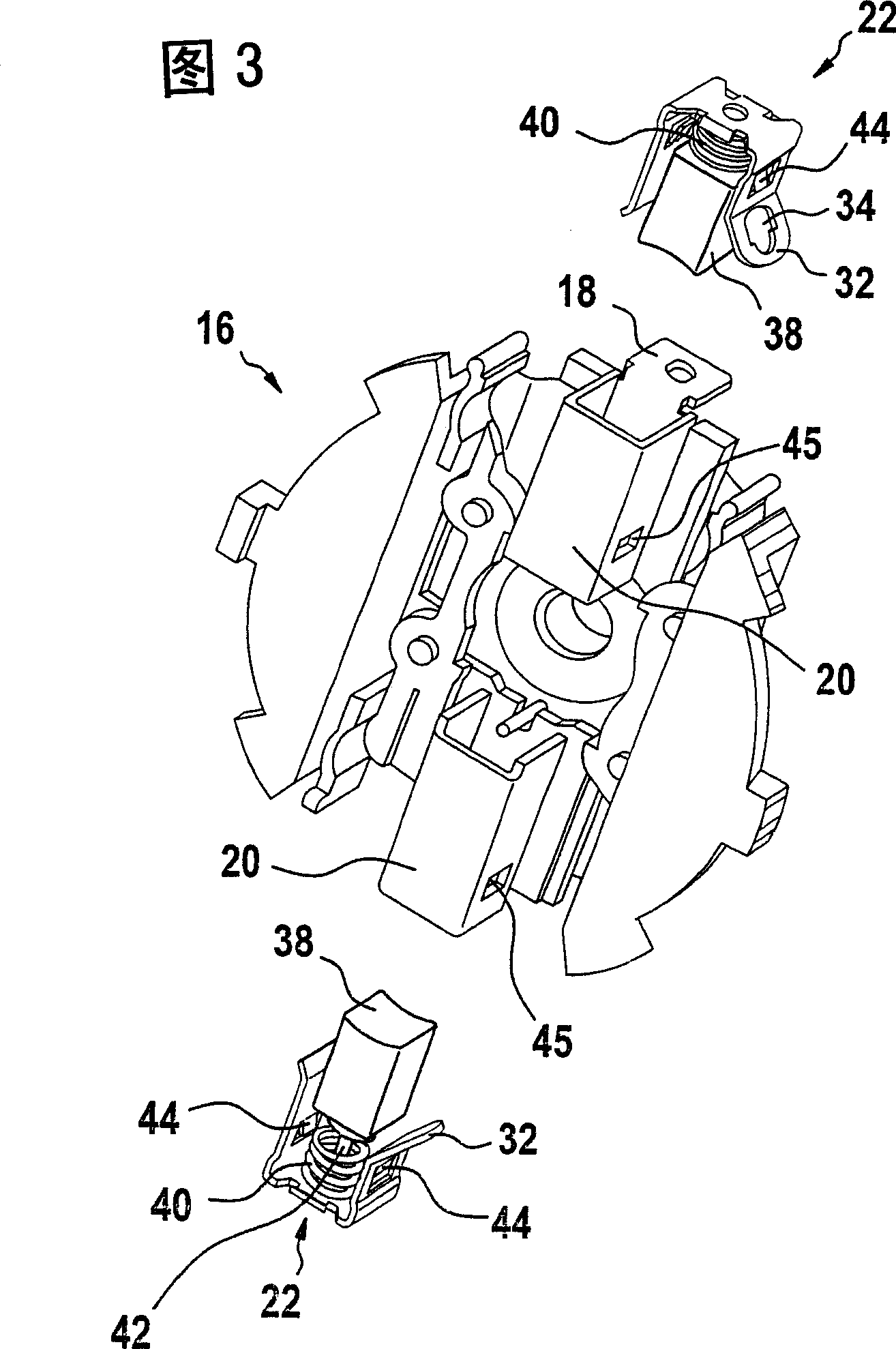
[0017] Two brush holders 20 protrude radially outward from the carbon brush plate 16 on two opposite sides, only the upper brush holder being visible. Each brush holder has an axially outward contact tongue 18 for connecting a cable, not shown, to a power supply, not shown. The brush holders 20 are each closed externally by a locking cap 22 consisting of a cover 24 with two lateral legs 26 , 28 which are secured to the brush by means of spring tongues 44 laterally offside. Grip 20 on. The one leg 28 has a...


PUM


Abstract

The invention relates to an electric motor (10) comprising a rotor, in addition to replaceable carbon brushes (38). One end of said brushes can be connected to a current source and the other end can be electrically connected to the rotor. The carbon brushes (38), each of which is mounted in a brush holder (20) so that it can be displaced longitudinally, are secured axially, in particular in a spring-loaded manner by a respective detent cap (22). The maintenance of said motor is facilitated by the fact that the detent cap (22) can be fixed to the brush holder (20) in a non-positive and / or positive fit and comprises at least one separate engagement element (34, 36) for a tool (46) that releases the detent cap (22) from the brush holder (20).

Description

[0001] current technology [0002] The invention relates to an electric motor according to the preamble of claim 1 . Background technique [0003] Electric motors are known whose carbon brushes are accessible from the outside through openings in the service cover without dismantling the housing. In this case, each carbon brush is connected to a locking cap, which can be locked in the form of a cover with the cylindrical brush holder and which presses the carbon brush into the interior of the brush holder, and in this case the carbon brush Spring-pretensioned contact with the rotor or with its commutator. [0004] Removal of the carbon brushes is accomplished by lifting the locking caps from the brush holders and pulling them out together through the maintenance opening. In this case, the detachment of the locking cap from the brush holder and the removal of the carbon brushes is troublesome and time-consuming. Contents of the invention [0005] The invention having the fe...

Claims


Application Information

Patent Timeline
IPC IPC(8): H02K13/00H01R39/38H02K5/14H02K15/00
CPCH02K5/148H02K15/00H01R39/385
Inventor 雷蒙德・布兰特斯凯恩雷纳托・沙勒
Owner SCINTILLA AKTIENGES
Why Eureka
Try Eureka