
A method of reinforcing a structure and a clamp

A technology of clamping device and magnetic clamping device, which is applied in the direction of workpiece clamping device, lamination device, transportation and packaging, etc., can solve the problems of damage to the surrounding structure, time-consuming installation and removal, etc., and achieve rapid implementation and rapid The effect of dismantling and reducing the effective cost

Inactive Publication Date: 2007-04-18
INTELLIGENT ENG BAHAMAS
View PDF5 Cites 0 Cited by
  • Summary
  • Abstract
  • Description
  • Claims
  • Application Information

AI Technical Summary

Problems solved by technology

Installation and removal of pressure plates is time consuming and the necessary welding and cutting can damage surrounding structures

Method used


Image

  • A method of reinforcing a structure and a clamp
  • A method of reinforcing a structure and a clamp
  • A method of reinforcing a structure and a clamp

Examples


Embodiment Construction

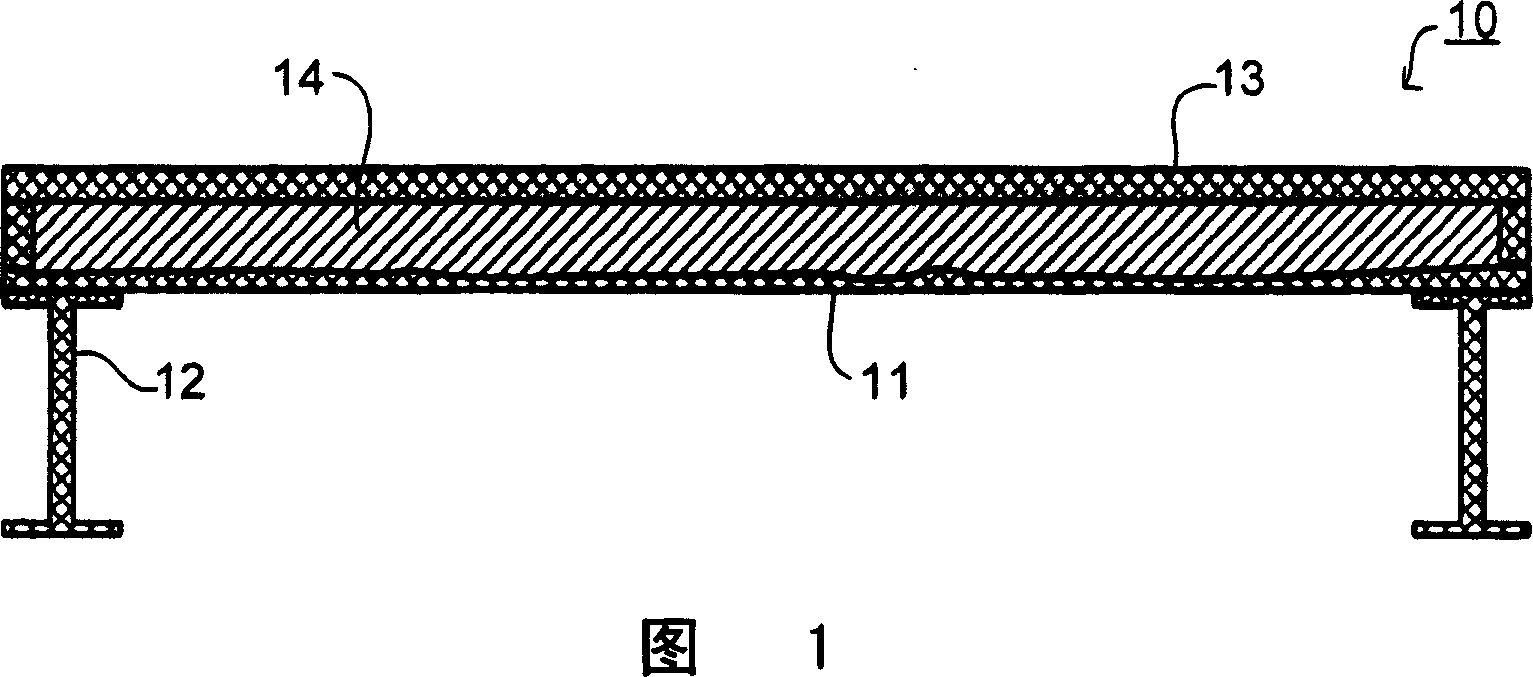
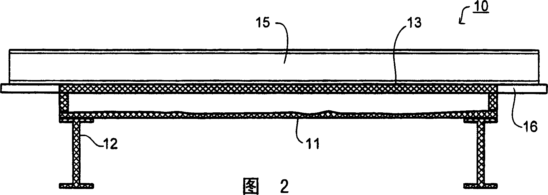
[0023] Figure 1 is a sectional view of the deck of a ro-ro ship which has been strengthened by the method of the present invention. A metal plate 11 forming the original deck is supported by beams 12 and bulb flats (not shown). Various pipes and cables (not shown) and fireproofing materials are attached to the underside of the metal plate 11 .

[0024] The metal plate 11 has an original thickness. For example the thickness of the deck of a ro-ro ship would typically be in the range of 10 mm to 20 mm. Typical corrosion and wear reduce the thickness of the metal plate 11 by approximately 0.15 mm per year. Under these environmental conditions, the sheet metal 11 needs to be replaced or strengthened after about twenty years of use.

[0025] The method of strengthening of the present invention consists in attaching a reinforcing metal layer 13 to the metal plate 11 of the existing structure. The metal layer 13 is arranged in spaced relation to the metal plate 11 whereby a cavit...


PUM

PropertyMeasurementUnit
thicknessaaaaaaaaaa
thicknessaaaaaaaaaa
elastic modulusaaaaaaaaaa

Abstract

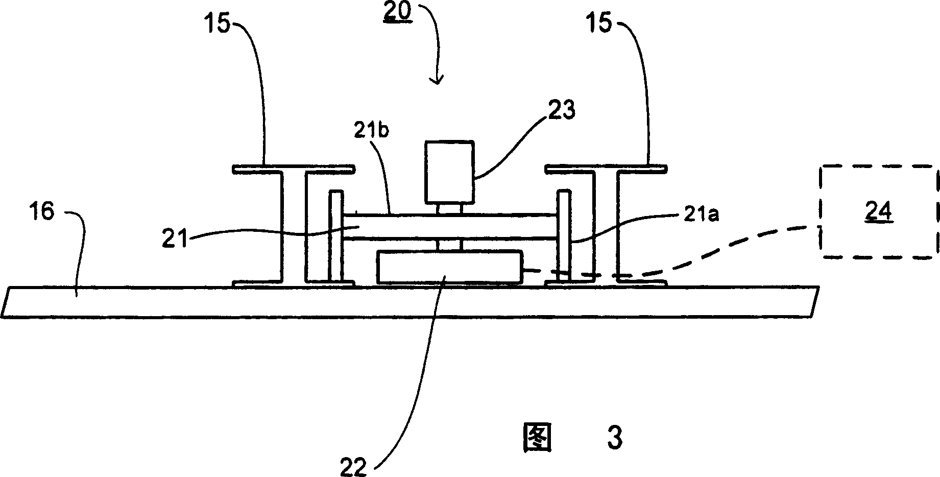
In performing an SPS overlay to reinforce an existing metal structure, restraint beams are held down by magnetic clamps.

Description

technical field [0001] The present invention relates to a method of strengthening and / or restoring and / or repairing existing metal structures, in particular existing metal panels of larger existing structures. More specifically, the method involves strengthening and / or restoring metal panels that have been reduced in thickness due to corrosion and / or wear during service and must therefore be replaced or reinforced. Background technique [0002] Structural sandwich panel components are described in US patent documents US5778813 and US6050208, both of which are incorporated herein by reference, which comprise a central elastomeric Core and bonded together the outer sheet metal, that is, the steel plate. These sandwich panel systems can be used in many forms of construction to replace reinforced steel plates, formed steel plates, reinforced concrete or composite steel-concrete structures, and greatly simplify the final structure, improving strength and structural performance (...

Claims


Application Information

Patent Timeline
Patent Type & Authority Applications(China)
IPC IPC(8): B32B27/40B32B7/02B32B15/08B63B3/68E04C2/284B32B37/24B63B3/48B63B9/00
CPCB63B3/48B63B2009/008B63B3/68B32B15/08B32B2311/00B32B2605/12B63B2005/245B63B9/00B32B37/24B63B81/00B63B71/00B25B11/00B32B27/40E04C2/26B32B2038/0076
Inventor T·H·R·肯尼迪K·J·案谷斯
Owner INTELLIGENT ENG BAHAMAS
Learn More