Movable steel gate plate and movable wall for dyke

A technology of movable walls and steel gates, applied in the direction of coastline protection, etc., can solve the problems of huge cost and heightening of dikes, and achieve the effects of reducing flood fighting costs, saving maintenance costs, and facilitating disassembly and assembly

Inactive Publication Date: 2003-04-09
HEILONGJIANG PROV WATER CONSERVANCY & HYDROPOWER SURVEY & DESIGN INST
View PDF0 Cites 9 Cited by
  • Summary
  • Abstract
  • Description
  • Claims
  • Application Information

AI Technical Summary

Problems solved by technology

[0009] After this flood, it is imperative to raise the height of the embankment. The Songhua River and Shanghai Bund have different but similar problems as New York and Paris. Every tree on the riverside has a story, and every small riverside The wooden house has its series of books, and a fixed flood wall will be built to close the entire riverside landscape and raise the height of the riverside park as a whole. Not only will the river no longer be visible in the urban area, but it will also cost a lot

Method used


Image

  • Movable steel gate plate and movable wall for dyke
  • Movable steel gate plate and movable wall for dyke
  • Movable steel gate plate and movable wall for dyke

Examples


Embodiment 1

[0031] Take the Harbin section of the Songhua River as an example using the embankment movable steel gate movable wall of the present invention, because this section has a 0.6-meter-high concrete cofferdam, so the described movable wall includes a 2.0-meter-high concrete cofferdam that is installed on the cofferdam. A group of connected individual rams 1 called the "General Section", and a 0.6-meter-high individual ram 2 (filled in the pedestrian passageway from the river embankment to the ship station and the river) and 2.0 meters high. In this way, if the height of the dam can be blocked by 0.6 meters according to the amount of flood, only 0.6 meters of gates should be installed at the gates that people usually pass through. A single ram is enough. If the water level needs to be increased by more than 0.6 meters, a 2.0-meter single ram 1 can be installed on the 0.6-meter single ram 2 to keep the same height as the general section, or other can be selected according to needs. ...

Embodiment 2

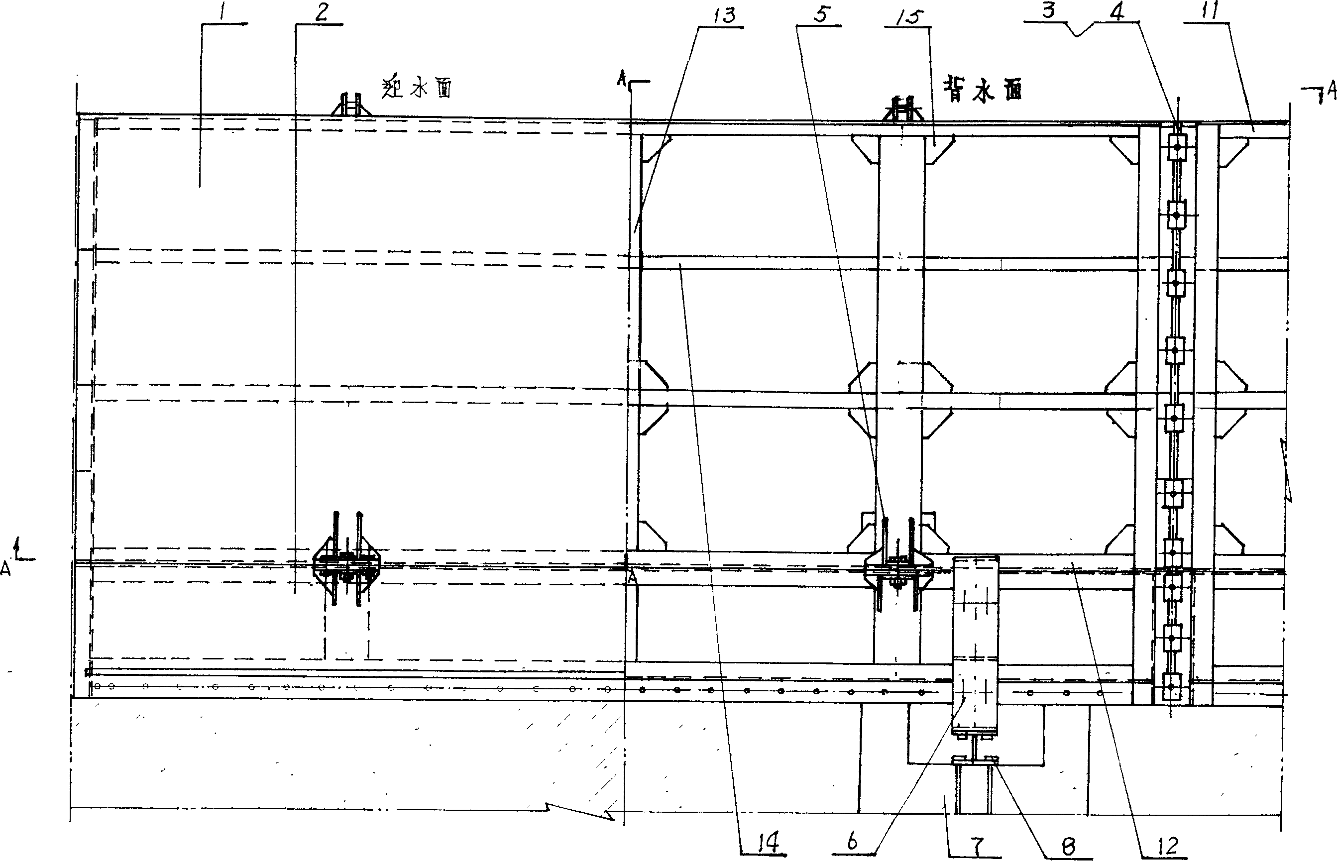
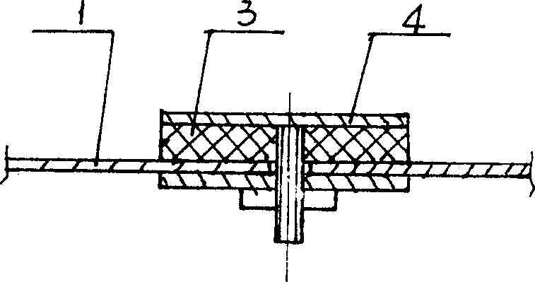
[0036] The movable steel ram movable wall of the embankment adopts a steel structure design, wherein the upper and lower sides of the single ram 1 or the single ram are fixed with an upper beam 11 and a lower beam made of section steel such as channel steel or square steel. 12. A longitudinal beam 13 is installed between the upper beam 11 and the lower beam 12. If a scheme with a height of more than 1.5 meters or a length of more than 1.5 meters is adopted, the space between the upper beam 11 and the lower beam 12 and the longitudinal beam Rigid reinforcing ribs 14 distributed vertically and horizontally should be housed, and the setting of reinforcing ribs is preferably no more than 1.5 meters in longitudinal and transverse distances, and angled reinforcing plates 15 can be installed between the reinforcing ribs.

[0037] If the height is less than 1 meter, no transverse reinforcing ribs can be added, and longitudinal ribs are arranged according to the length of the single gat...

Embodiment 3

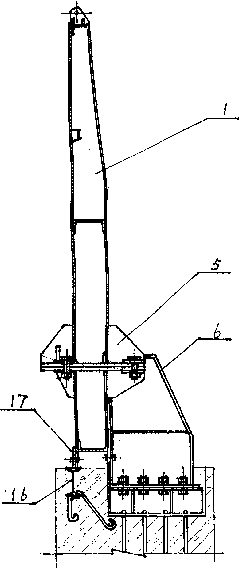
[0040] In the movable steel ram movable wall of the embankment, the bottom surface of the single ram 1 or the single ram 2 can be fixed by bolts 16 pre-embedded on the cofferdam, so that the force on the single ram is within Decomposition occurs during transmission to the foundation, reducing the overturning moment and horizontal thrust of the single ram to the support. A sealing strip 17 is installed between the bottom surface of the ram and the cofferdam to prevent leakage.


PUM


Abstract

The present invention relates to assembled movable dam for resistinf flood and tide water. The movable steel plate wall of dyke includes two groups of single gate plates connected via sealing strips and holding strips. The single gate plates are fixed to dyke via support. The present invention is used in reconstructing available dyke and its construction has no effect on available dyke height, peripheral buildings and available scenes.

Description

[0001] Technical field: This product is an assemblable movable dam for preventing sudden flood or tide. Background technique: [0002] When human beings began to choose a place to live, they often chose places with water sources such as rivers and seas. After developing into cities, the construction of embankments on river banks or coasts has become an important issue. [0003] Due to the tidal changes of river water or sea water in nature, especially river floods caused by heavy rain, and changes in the height of the river bed, the water level is constantly changing. Once a spring tide or flood peak occurs, the water level exceeds the embankment, which will cause great harm to people's lives. , which makes people request that the embankment be continuously raised according to the level of once in fifty years or even once in a hundred years. [0004] The water is covered by the earth, and the way to prevent floods in ancient and modern China and abroad is to increase the heigh...

Claims


Application Information

Patent Timeline
Patent Type & Authority Applications(China)
IPC IPC(8): E02B3/12
Inventor 戴春胜刘加海李芳佩
Owner HEILONGJIANG PROV WATER CONSERVANCY & HYDROPOWER SURVEY & DESIGN INST
Why Eureka
Try Eureka