Forming die for component in polyhedron

A technology for forming molds and polyhedrons, which can be used in molds, building components, reinforcement molding, etc., and can solve the problems of inconvenient demoulding and easy damage of thin-walled boxes.

Inactive Publication Date: 2006-02-01
湖南邱则有专利战略策划有限公司
View PDF3 Cites 9 Cited by
  • Summary
  • Abstract
  • Description
  • Claims
  • Application Information

AI Technical Summary

Problems solved by technology

For example, the female mold, as can be seen from their drawings, is surrounded by the side mold surface and the bottom mold surface. This kind of female mold is the female mold of the overall template. Wall tubes or thin-walled boxes are easily damaged, therefore, it is urgent to develop a new type of polyhedral component forming die

Method used


Image

  • Forming die for component in polyhedron
  • Forming die for component in polyhedron
  • Forming die for component in polyhedron

Examples


Embodiment Construction

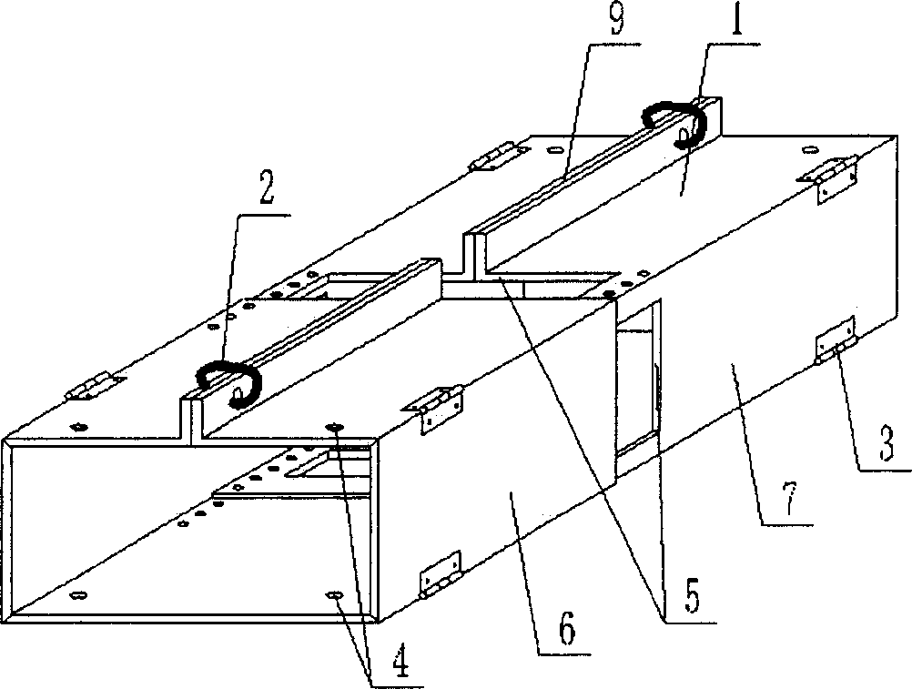
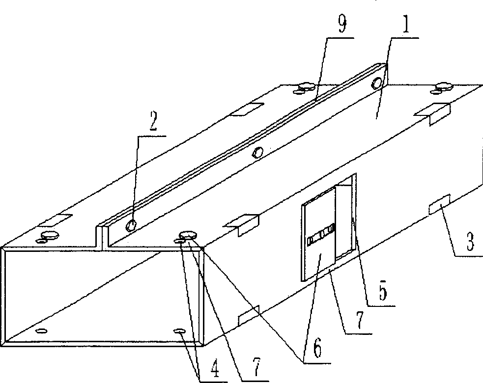
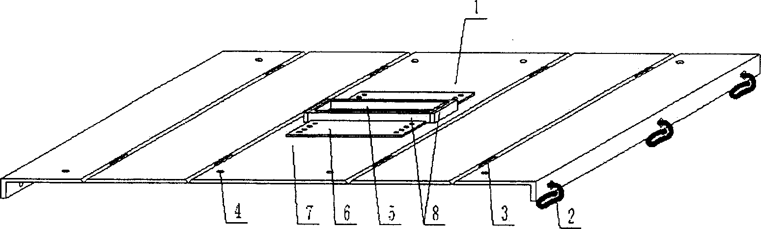
[0060] The present invention will be further described below in conjunction with the accompanying drawings and embodiments. In each accompanying drawing, 1 is a template, 2 is a fastening member, 3 is a rotating part, 4 is a through hole, and 5 is a through groove. In the following accompanying drawings, those with the same number have the same description. Such as figure 1 As shown, the multiple templates 1 of the polyhedral component forming mold are connected by a rotating part 3, and the connected templates 1 can rotate relatively, and the mold closing port 9 is arranged on the die surface between the two corners of the top. When the templates are closed at the top, they can be closed by Fasteners 2 are fixed to form a polyhedral component forming mold; the mold shown in this embodiment is connected side by side by five templates 1 in sequence, and the template 1 is provided with a through hole 4 and a through groove 5, and the size of the through groove 5 can be moved by ...


PUM


Abstract

A mould for forming the polygonal structrural member is composed of the form boards, the turnable parts for connecting said form boards in turnable mode, and the fasteners for fastening the closed form boards. It features that at least 3 form boards are sequentially and parallelly connected by said turnable parts, at one form board has through holes (or slots) and at least one said through hole (or slot) has regulatable size. Its advantages are convenient demoulding and high strength.

Description

(1) Technical field [0001] The invention relates to a polyhedral component molding die, more precisely, to a polyhedral component molding die for construction. (2) Background technology [0002] At present, cast-in-place reinforced concrete hollow slabs, especially the non-core-pulling hole-forming process of cast-in-situ reinforced concrete hollow slabs, are generally filled with thin-walled tubes or thin-walled boxes, which can meet the needs of various hollow slabs for evacuating concrete. For example, the publication number applied by the applicant on May 29, 2002 is CN1462680A, and the title is "Hollow Tube Forming Tool", which is characterized in that it includes two interface edges, a stretchable elastic cylinder, a brace, a tightening piece, an interface The side is fixed on the wall edge of the tension-type elastic cylinder along the length direction, the supporting part is wrapped in the end of the tension-type elastic cylinder, and the tightening part is locked on...

Claims


Application Information

Patent Timeline
Patent Type & Authority Applications(China)
IPC IPC(8): B28B21/82B28B21/56B28B7/04B28B7/16B28B7/26B28B7/28E04B5/16
Inventor 邱则有
Owner 湖南邱则有专利战略策划有限公司
Why Eureka
Try Eureka