

Piezoelectricity libration plate, piezoelectric vibrator and piezoelectric oscillator
A piezoelectric vibrating plate and piezoelectric vibrator technology, which is applied in the manufacture/assembly of piezoelectric devices/electrostrictive devices, power oscillators, piezoelectric/electrostrictive devices, etc. The value is not clear, etc., to achieve the effect of stabilizing the resonance frequency, reducing vibration displacement, and improving the CI value
- Summary
- Abstract
- Description
- Claims
- Application Information
AI Technical Summary
Problems solved by technology
Method used
Image

Examples
Embodiment 1
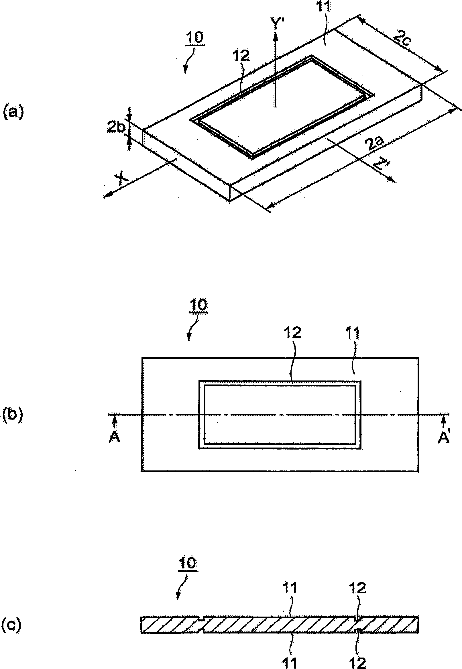
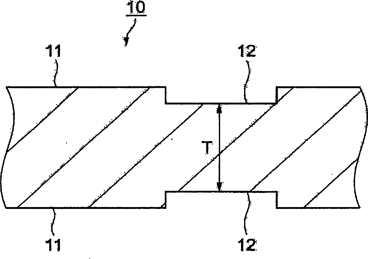
[0079] figure 1 and figure 2 It is a schematic diagram illustrating the vibrating element of the first embodiment of the present invention. figure 1 (a) is a perspective view of a vibrating plate, figure 1 (b) is a top view of the vibrating plate, figure 1 (c) is the A-A sectional view of the figure (b), figure 2 yes figure 1 Partial enlarged view of the groove in (c).
[0080] The vibrating piece 10 as a piezoelectric vibrating piece is designed, for example, to have a resonance frequency of 27 MHz, an X-side ratio (the ratio of the dimension in the X-axis direction of the vibrating piece to the thickness of the vibrating piece) of 33, and a Z' side ratio (Z' of the vibrating piece). The ratio of the dimension in the axial direction to the thickness of the vibrating piece) was 21. Here, the thickness of the central portion of the vibrating piece 10 is about 62 μm.
[0081] The Y' axis and Z' axis of the vibrating piece 10 are new coordinate axes formed by rotating cl...
Embodiment 2
[0109] Next, in Example 2, an example in which the vibrating piece has two grooves will be described.
[0110] Figure 10 and Figure 11 It is a schematic diagram explaining the vibrating piece of Example 2 of the present invention. Figure 10 (a) is a top view of the vibrating plate, Figure 10 (b) is a top view of the vibrating plate, Figure 10 (c) is the A-A sectional view of the figure (b), Figure 11 yes Figure 10 Partial enlarged view of the groove in (c).
[0111] exist Figure 10 , Figure 11 In , the same symbols are assigned to the same structures as those in Example 1, and explanations thereof are omitted.
[0112] On the main surface 11 of the vibrating piece 10 , a circumferential groove portion surrounding the center of the main surface 11 in a square shape, a first groove portion 12 and a second groove portion 13 are formed. The first groove portion 12 and the second groove portion 13 are formed in the same shape facing the front and back of the princ...
Embodiment 3
[0123] Next, an example in which the vibrating piece has three grooves in Example 3 will be described.
[0124] Figure 14 and Figure 15 It is a schematic diagram illustrating a vibrating piece according to Embodiment 3 of the present invention. Figure 14 (a) is a top view of the vibrating plate, Figure 14 (b) is a top view of the vibrating plate, Figure 14 (c) is the A-A sectional view of the figure (b), Figure 15 yes Figure 14 Partial enlarged view of the groove in (c).
[0125] exist Figure 14 , Figure 15 In , the same symbols are assigned to the same structures as those in Embodiment 1 and Embodiment 2, and description thereof will be omitted.
[0126] Such as Figure 14 As shown in (a) and (b), on the main surface 11 of the vibrating piece 10, a circumferential groove portion surrounding the center of the main surface 11 in a square shape, a first groove portion 12, a second groove portion 13, and a third groove portion are formed. Section 14. The first...
PUM
 Abstract
Description
Claims
Application Information