Center convergence optimization in a projection display apparatus

A technology of display devices and devices, which is applied in the direction of using projection devices, image reproducers, instruments, electrical components, etc., and can solve the problems of gradual rounding errors, convergence errors, etc.

Inactive Publication Date: 2005-09-21
THOMSON LICENSING SA
View PDF0 Cites 0 Cited by
  • Summary
  • Abstract
  • Description
  • Claims
  • Application Information

AI Technical Summary

Problems solved by technology

If multiple such centering adjustments are made without re-running the sensor, which finds a routine that eras

Method used


Image

  • Center convergence optimization in a projection display apparatus
  • Center convergence optimization in a projection display apparatus
  • Center convergence optimization in a projection display apparatus

Examples


Embodiment Construction

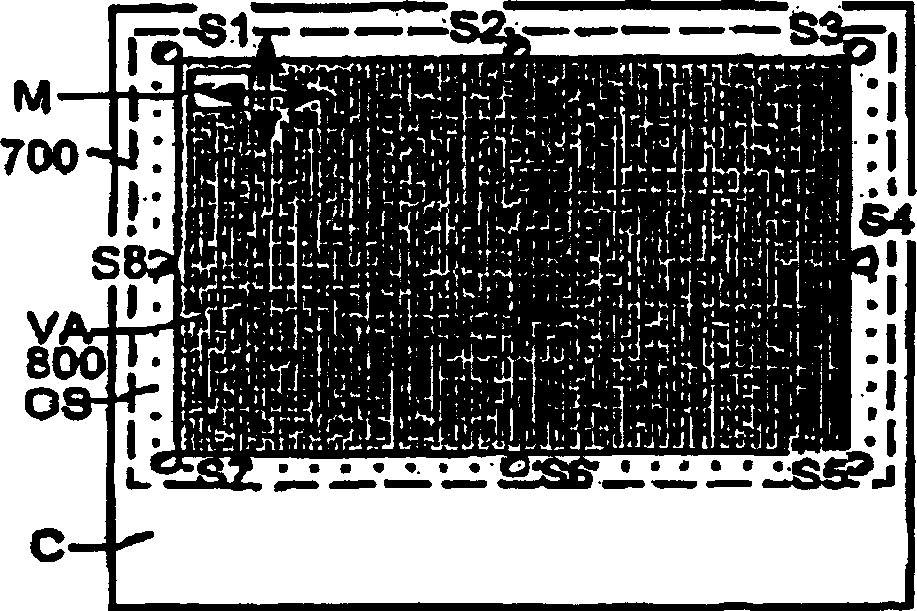
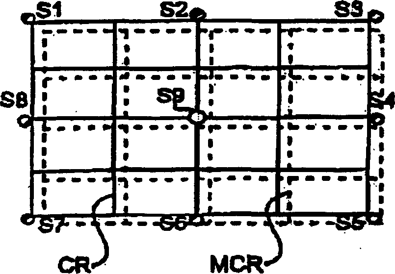
[0013] Figure 1A is a front view of a video projection display. The projection display includes a plurality of cathode ray tubes whose raster-scanned images can be projected onto a display screen 700 . A housing supports and surrounds the display screen 700 and provides a graphics display area 800 slightly smaller than the display screen. The dotted line in the display screen 700 indicates an edge area hidden in the casing C, as shown in the area OS in the figure, which can be illuminated together with the raster scan image when working in the overscan mode. The photosensors are located adjacent the perimeter of the display screen 700 , within the concealed border area, and outside the display area 800 . Figure 1A Eight sensors are shown, all positioned on a measurement grid (not shown) to provide measurements at the center and corners of the edge of the display. Thus, with these grid-like positioned sensors, it is possible to measure correspondingly formatted electronicall...


PUM


Abstract

Progressive rounding error and convergence error encountered due to multiple use of a center correction adjustment (820) of an image of a video projection display is reduced by calculating a 3 x 3 matrix (770) for a moved color signal where the non center matrix values represent the difference between the initially measured sensor values (Si1,...,Si8) stored at initial alignment (720), and stored most recently measured sensor values (Sp1,...,Sp8). The matrix center value (860) is the sum of the averaged values calculated from the edge center errors, the stored sum of previous moves (MS) and the current move (CP). Rerun of the sensor finding routine (745) resets the stored move sum to zero.

Description

[0001] This application claims priority under U.S.C. Section 35 119(e) to U.S. Provisional Application No. 60 / 399,865, filed July 31, 2002, entitled "Centre Convergence Optimization in Projection Display Devices." technical field [0002] This invention relates to the field of video projection displays and, in particular, to the correction of minor convergence errors at the center of the projected image following automatic convergence correction. Background technique [0003] In video projection displays, geometric raster distortion is due to the physical location of the cathode ray display tube. This raster distortion is exacerbated by the use of display surfaces with concave curvature and the inherent magnification in the light projection channel. The projected image consists of three scanned rasters that need to be aligned with each other on the display. Precise superposition of the three projected images requires adjustment of multiple wavelengths to compensate for geom...

Claims


Application Information

Patent Timeline
IPC IPC(8): G03B21/00H04NH04N1/00H04N9/28H04N9/31H04N17/00
CPCH04N9/28H04N9/31
Inventor 约翰·巴雷特·乔治安赫拉·勒妮·伯内特
Owner THOMSON LICENSING SA
Why Eureka
Try Eureka