Rotatable cutting tool

A technology of rotating cutters and cutter bodies, applied in the field of improved actuators and rotatable cutters, can solve problems such as operation damage of adjustment devices

Inactive Publication Date: 2005-09-28
瓦莱尼特股份有限公司
View PDF3 Cites 6 Cited by
  • Summary
  • Abstract
  • Description
  • Claims
  • Application Information

AI Technical Summary

Problems solved by technology

Such seals, if not regularly replaced and repaired, are a common source of hydraulic fluid leaks that impair the operation of the adjusting device

Method used


Image

  • Rotatable cutting tool
  • Rotatable cutting tool
  • Rotatable cutting tool

Examples


Embodiment Construction

[0012] The invention will be described with reference to a preferred embodiment shown in the accompanying drawings. Also preferred embodiments explain the features of the invention. It is not the intention of this application to limit the invention to the specific details of the preferred embodiment.

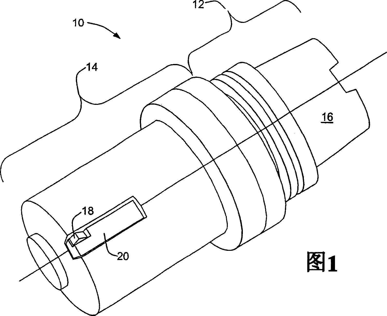
[0013] A rotatable tool 10 shown in FIG. 1 includes a shank portion 12 and a cutting portion 14 . The shank portion 12 is adapted to be mounted on a joint 16 for connection to a tool drive such as a rotatable spindle of a machine tool. The adapter 16 may be adapted to a tool drive spindle of a machine tool lacking an automatic tool change mechanism. Moreover, the joint 16 is preferably consistent with the standard to ensure compatibility with the standard automatic tool changer, such as the well-known standard of this joint: HSK; German Industrial Standard (DIN) International Organization for Standardization (ISO) / Draft International Standard (DIS) 12164-1&-2; American Nation...


PUM


Abstract

A rotatable cutting tool has a shank portion for coupling to a tool driving device and a cutting portion to which is attached at least one support member for retention of a replaceable cutting element. The support member is so arranged to permit displacement of at least the portion thereof retaining the cutting element whereby the position of the cutting element relative to the body of the cutting tool may be changed by such displacement. A totally enclosed hydraulic force multiplier is mounted within an internal cavity of the cutting tool. The force multiplier is responsive to a control force to effect the displacement of the support member, the control force advantageously supplied by application of pneumatic pressure.

Description

technical field [0001] The invention relates to a tool, in particular a rotatable tool having at least one cutting element, the position of which relative to the tool can be adjusted by remotely controlling an adjustment device. More particularly, the present invention relates to improved actuators for remotely adjusting the relative positions of rotatable tool cutting members. Background technique [0002] Known rotatable knives that include adjustable cutter positions use different means to effectively change the cutting element position. An example of such a rotatable knife using mechanical actuation means is explained in patent application EP1123766. An example of a rotatable cutter using a hydraulic actuation device requiring hydraulic fluid is explained in Japanese Utility Model Application No. 62-201231. Knives of this type have the inherent drawback of requiring a connection to supply hydraulic fluid through the tool drive. US Patent US4941782 illustrates a tool i...

Claims


Application Information

Patent Timeline
Patent Type & Authority Applications(China)
IPC IPC(8): B23B29/034C12N15/38
CPCB23B2270/027Y10T408/8588Y10T408/85843B23B29/03457Y10T408/8583B23B2270/025B23B29/03B23B29/12B23B29/02
Inventor 詹姆斯·R·布罗克詹姆斯·J·鲁宾逊
Owner 瓦莱尼特股份有限公司
Why Eureka
Try Eureka