Gas blast circuit breaker

A technology for compressing gas and circuit breakers, which is applied to high-pressure air circuit breakers, circuits, electrical components, etc., and can solve problems such as overpressure valve wear and tear

Inactive Publication Date: 2013-03-20
SIEMENS AG
View PDF5 Cites 6 Cited by
  • Summary
  • Abstract
  • Description
  • Claims
  • Application Information

AI Technical Summary

Problems solved by technology

[0004] The pressure relief valve arranged at the outlet is loaded mechanically but also thermally, so that wear on the pressure relief valve can occur

Method used


Image

  • Gas blast circuit breaker
  • Gas blast circuit breaker
  • Gas blast circuit breaker

Examples


Embodiment Construction

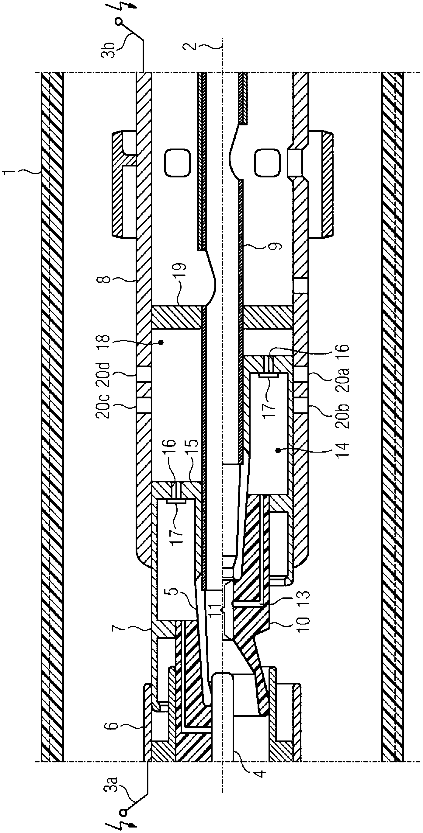
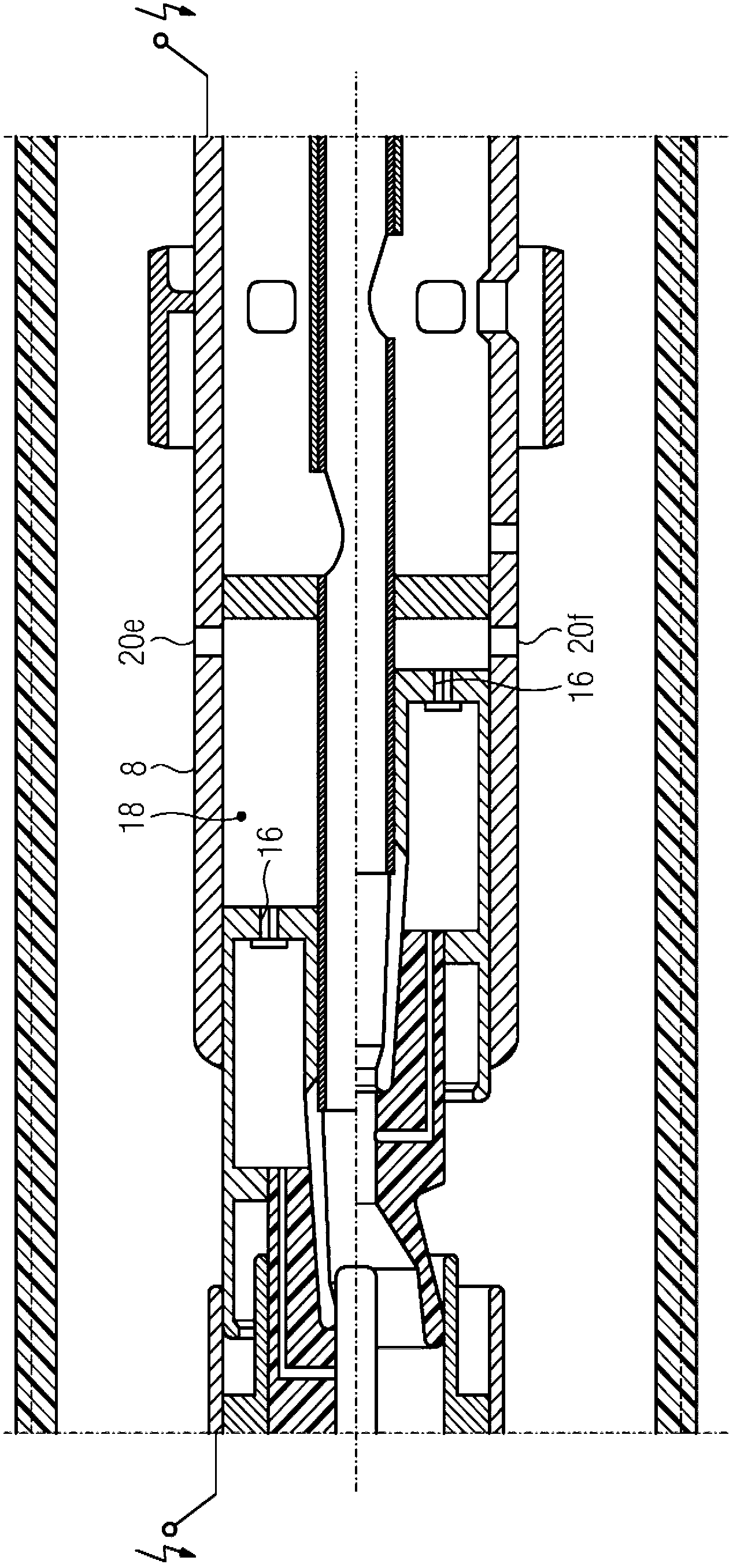
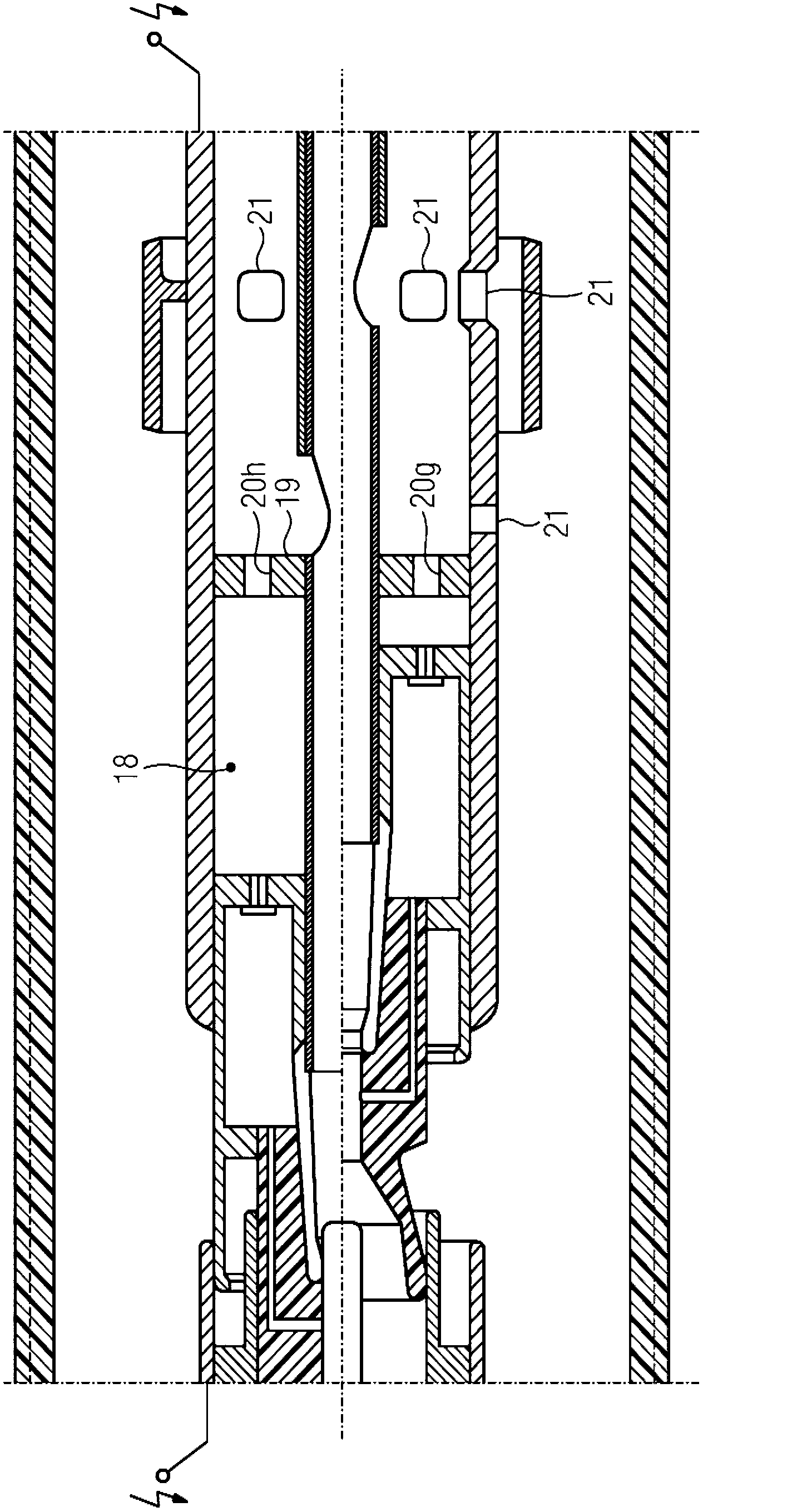
[0037] First, for example for figure 1 , figure 2 with image 3 Explain the structure and mode of action of compressed gas circuit breakers. Here at figure 1 , figure 2 with image 3 The same reference numerals are used for the same type of structural parts, and alternative reference numerals are used only for mutually different details.

[0038] What all three figures have in common is that the symmetry axis 2 divides the figure into a first half and a second half. The drawings respectively show the on state of the compressed gas circuit breaker in the first half of the figure and the open state of the compressed gas circuit breaker in the second half of the figure.

[0039] figure 1 The cross-section of the compressed gas circuit breaker is shown in the cross-sectional view. The compressed gas circuit breaker has an enclosure 1. The packaging housing 1 is here configured to be substantially tubular and oriented coaxially to the axis of symmetry 2. Here, the packaging case ...


PUM


Abstract

The invention relates to a circuit breaker comprising a first contact (4) and a second contact (5). An electric arc zone is disposed between the contacts (4, 5). A feed channel (13) opens into the electric arc zone, connecting the electric arc zone to a hot gas reservoir volume (14). The hot gas reservoir volume (14), in turn, is connected to a compression volume (18). An outflow opening (20a, 20b, 20c, 20d, 20e, 20f, 20g, 20h) is disposed in a wall (8) of the compression volume (18). The outflow opening (20a, 20b, 20c, 20d, 20e, 20f, 20g, 20h) is permanently open at least in the contacting state of the contacts (4, 5).

Description

Technical field [0001] The present invention relates to a compressed gas circuit breaker. The switch has an arc zone arranged between a first contact and a second contact. The arc zone is connected to a hot gas storage volume through a supply channel, and the hot gas storage volume is It is connected with a variable-volume compression volume through an overflow channel; and has a wall with at least one outflow port that defines the boundary of the compression volume. Background technique [0002] Such a compressed gas circuit breaker is described, for example, in the utility model DE20015563U1. This type of compressed gas circuit breaker has a first contact and a second contact, and the arc zone extends between the first contact and the second contact. Provides guidance for the arc in the arc zone. The arc zone is connected to the hot gas storage volume through the supply channel, wherein a variable compression volume is connected to the hot gas storage volume. The hot gas sto...

Claims


Application Information

Patent Timeline
Patent Type & Authority Applications(China)
IPC IPC(8): H01H33/91
CPCH01H33/91H01H2033/908
Inventor R-M.塞纳特
Owner SIEMENS AG
Why Eureka
Try Eureka