Minitype electronic lock

An electronic lock and miniature technology, applied in building locks, non-mechanical transmission-operated locks, buildings, etc., can solve the problems of low security, complex structure, weak functions, etc., and achieve a high degree of intelligence, reliable connection, Reasonable effect of structural design

Inactive Publication Date: 2005-10-26
吴斐
View PDF0 Cites 0 Cited by
  • Summary
  • Abstract
  • Description
  • Claims
  • Application Information

AI Technical Summary

Problems solved by technology

[0002] At present, the structure of the miniature induction electronic lock is complicated, the security is not high, and the function is not strong.

Method used


Image

  • Minitype electronic lock
  • Minitype electronic lock
  • Minitype electronic lock

Examples


Embodiment Construction

[0021] The present invention will be described in further detail below with reference to the accompanying drawings.

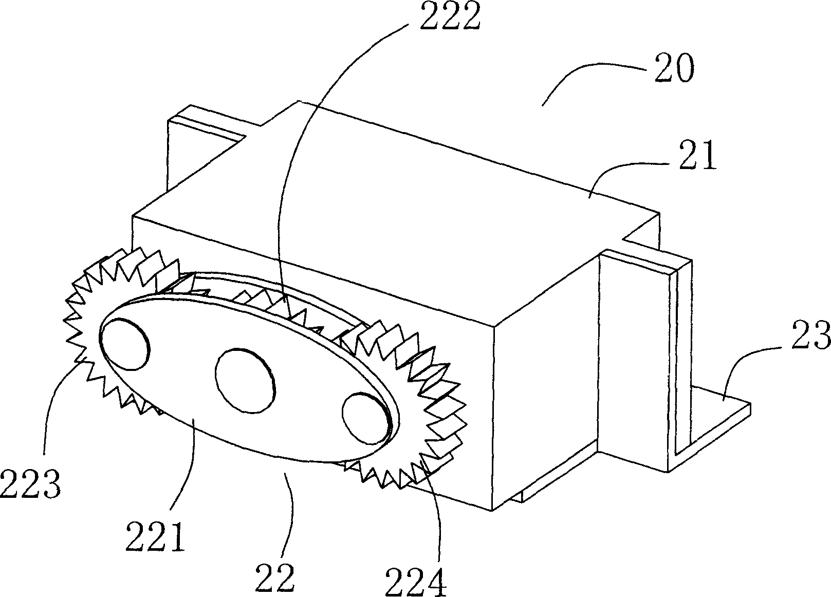
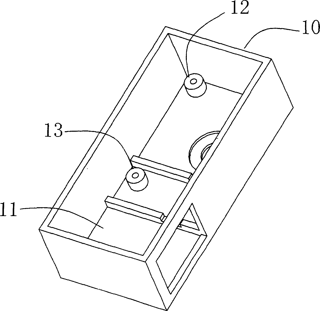
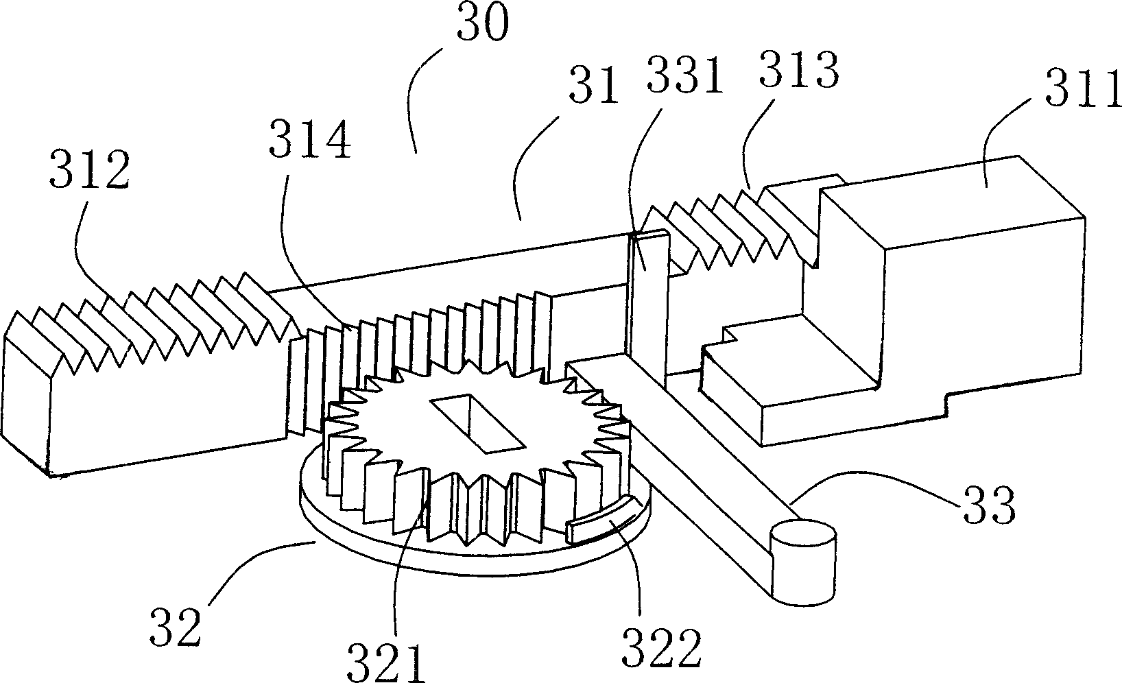
[0022] See Figure 6 , figure 2 The miniature electronic lock includes a lock tongue mechanism 40 controlled by a control mechanism 20 in the lock box 10 through a drive mechanism 30, and a storage box 11 that is provided with a lock tongue 41 at a location outside the lock box 10 corresponding to the lock tongue 41. The lock tongue The side of the bolt support frame 42 of the mechanism 40 is provided with a locking hole 421 through which the head end 311 of the rod 31 of the driving mechanism 30 is penetrated. The middle part of the side of the rod 31 of the driving mechanism 30 and the two ends of the adjacent vertical surface The racks 312 and 313 at both ends of the drive mechanism 30 pull rod 31 are engaged with the gear set 22 fixed on the output shaft of the motor 21 of the control mechanism 20 of the external power supply. The drive mechanism 30 pulls the r...


PUM


Abstract

The present invention relates to a miniature electronic lock, including the control mechanism in lock box and the lock bolt controlled by driving mechanism. There through equips a lock stopping hole for the pull rod head of the driving mechanism at the side of the lock bolt bracket. The middle of one surface of the driving mechanism pull rod and both ends of its near and vertical surface respectively equip racks. The racks at both ends of driving mechanism pull rod mesh on the gear wheel group fixed on the output axis of the control mechanism electromotor of the external electrical source. The gear wheel group includes two elliptic plywood to clip the main gear wheel of the gemel and the driven gear wheel respectively meshed with the main gear wheel from two ends gemel of the two elliptic plywood. When driven by the electromotor, the main gear wheel turns to the direction of driven gear wheel, which automatically meshs with the pull rod gear wheel through running outside force, to drive the pull rod move forward to the edental strip segment to achieve the separating and jointing state. Whereas when the main gear wheel turns from the direction of driven gear wheel, which automatically meshs with the pull rod gear wheel through running outside force, to drive the pull rod move backward to the edental strip segment to achieve the separating and jointing state.

Description

Technical field [0001] The invention relates to a miniature electronic lock controlled by a control circuit. Background technique [0002] At present, the structure of the miniature induction electronic lock is complicated, the safety is not high, and the function is not strong. Summary of the invention [0003] The purpose of the present invention is to overcome the above shortcomings in the prior art and provide a miniature electronic lock with simple structure, safety and reliability, low cost and wide application range. [0004] The purpose of the present invention can be achieved by the following measures: [0005] This kind of miniature electronic lock includes a lock bolt mechanism controlled by a drive mechanism by a control mechanism in the lock box, and a bin box that accommodates the lock tongue provided at the corresponding lock tongue position outside the lock box. Its special feature is: the lock tongue mechanism The side of the bolt support frame is provided with ...

Claims


Application Information

Patent Timeline
Patent Type & Authority Applications(China)
IPC IPC(8): E05B47/06
Inventor 吴斐
Owner 吴斐
Why Eureka
Try Eureka