Relatively prime mode parallel counter based on congruence theory

A technology of counter and ring counter, applied in the direction of synchronous pulse counter, continuous cycle pulse counter, etc., can solve the problems of reduced maximum counting frequency, many hardware resources, and rarely used, etc., and achieve the effect of relieving the pressure of time interpolation

Inactive Publication Date: 2005-10-26
HARBIN INST OF TECH
View PDF0 Cites 2 Cited by
  • Summary
  • Abstract
  • Description
  • Claims
  • Application Information

AI Technical Summary

Problems solved by technology

However, since the order of the output state of this counter is not convenient to describe, and because this counter uses more hardware resources, it is rarely used in actual engineering applications
Synchronous counters with existing structures generally have the problem that as the number of flip-flops in the counter increases, the maximum counting frequency will inevitably decrease.

Method used


Image

  • Relatively prime mode parallel counter based on congruence theory
  • Relatively prime mode parallel counter based on congruence theory

Examples


specific Embodiment approach 1

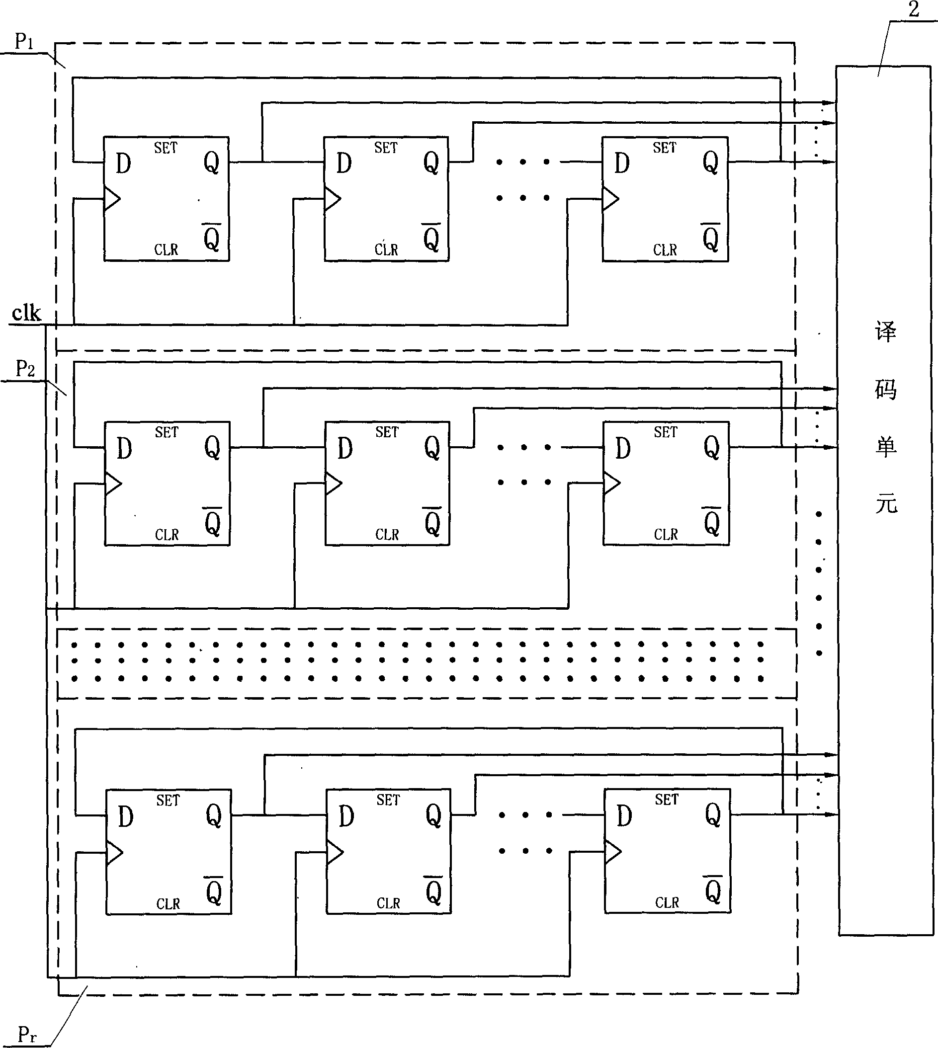
[0007] Specific implementation mode one: the following combination figure 1 This embodiment will be specifically described. It consists of a first synchronous ring counter P 1 , the second synchronous ring counter P 2 ...the rth synchronous ring counter P r Composed of decoding unit 2, the first synchronous ring counter P 1 ~rth synchronous ring counter P r The numbers of flip-flops in any two synchronous ring counters are prime numbers to each other, the clock pulse input terminals of the flip-flops in all synchronous ring counters are connected together and connected to the clock pulse signal clk, each trigger in all synchronous ring counters The positive output terminal or the negative output terminal of the converter are respectively connected to one input terminal of the decoding unit 2. All the flip-flops in this embodiment use "D" flip-flops, the input end of the first flip-flop of each synchronous ring counter is connected with the output end of the end flip-flop,...

specific Embodiment approach 2

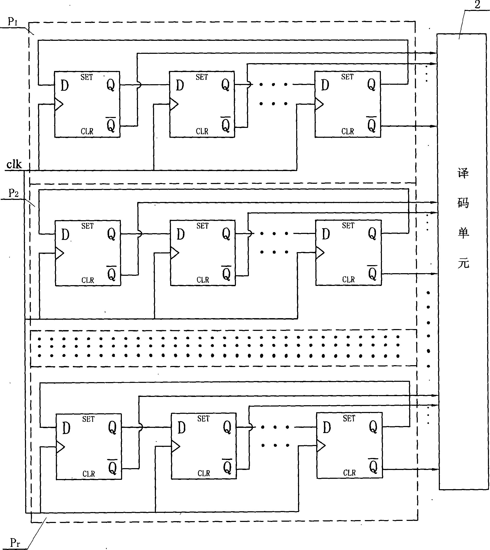
[0008] Specific implementation mode two: the following combination figure 2 This embodiment will be specifically described. It consists of a first synchronous ring counter P 1 , the second synchronous ring counter P 2 ...the rth synchronous ring counter P r Composed of decoding unit 2, the first synchronous ring counter P 1 ~rth synchronous ring counter P r The numbers of flip-flops in any two synchronous ring counters are prime numbers to each other, the clock pulse input terminals of the flip-flops in all synchronous ring counters are connected together and connected to the clock pulse signal clk, each trigger in all synchronous ring counters The inverting output ends of the switches are connected to one input end of the decoding unit 2 respectively. All the flip-flops in this embodiment are "D" flip-flops.


PUM


Abstract

A relative prime modulo parallel counter based on the congruent theory relates to a counter of synchronous shift register type composed of a first, a second synchronous ring counters, and a decode unit, among which, the numbers of triggers in any two synchronous ring counters from the first to r are prime mutually, the clock pulse input ends of all synchronous ring counters are connected and linked to the clock pulse signals, the positive output or negative output end of each trigger in all said counters are connected to an input end of the decode unit. It uses the counter as its basic component and numbers of triggers in each are prime mutually, so a large count can be got with only a few ring counters.

Description

Technical field: [0001] The present invention relates to a synchronous shift register type counter. Background technique: [0002] With the rapid development of science and technology, modern society has put forward higher and higher requirements for high-speed precision measurement in the field of electronic testing. As the technical foundation of precise time measurement and frequency measurement, high-speed counting technology is a key research topic in the field of electronic measurement. A counter is a component that reflects state changes in a digital system, and the speed of change is a key parameter of the counter, which directly determines whether the counter is suitable for a certain digital system. There are many ways to classify counters. From whether the changes of each output bit are synchronous, they can be divided into synchronous counters and asynchronous counters. Synchronous counters are generally composed of flip-flops and logic gates. Gate delays and l...

Claims


Application Information

Patent Timeline
Patent Type & Authority Applications(China)
IPC IPC(8): H03K23/54
Inventor 付平孟升卫乔家庆尹洪涛刘兆庆
Owner HARBIN INST OF TECH
Why Eureka
Try Eureka