Electrically isolated power and data coupling system suitable for portable equipment

A technology of electrical insulation and coupling system, which is applied in the direction of power network operating system integration, transmission system, electrical components, etc., and can solve problems such as interference with RF links of monitoring instruments

Inactive Publication Date: 2005-11-09
DRAEGER MEDICAL SYST INC
View PDF0 Cites 18 Cited by
  • Summary
  • Abstract
  • Description
  • Claims
  • Application Information

AI Technical Summary

Problems solved by technology

This instrument induces unpredictable amounts of RF energy and may interfere with the RF link of monitoring instruments

Method used


Image

  • Electrically isolated power and data coupling system suitable for portable equipment
  • Electrically isolated power and data coupling system suitable for portable equipment
  • Electrically isolated power and data coupling system suitable for portable equipment

Examples


Embodiment Construction

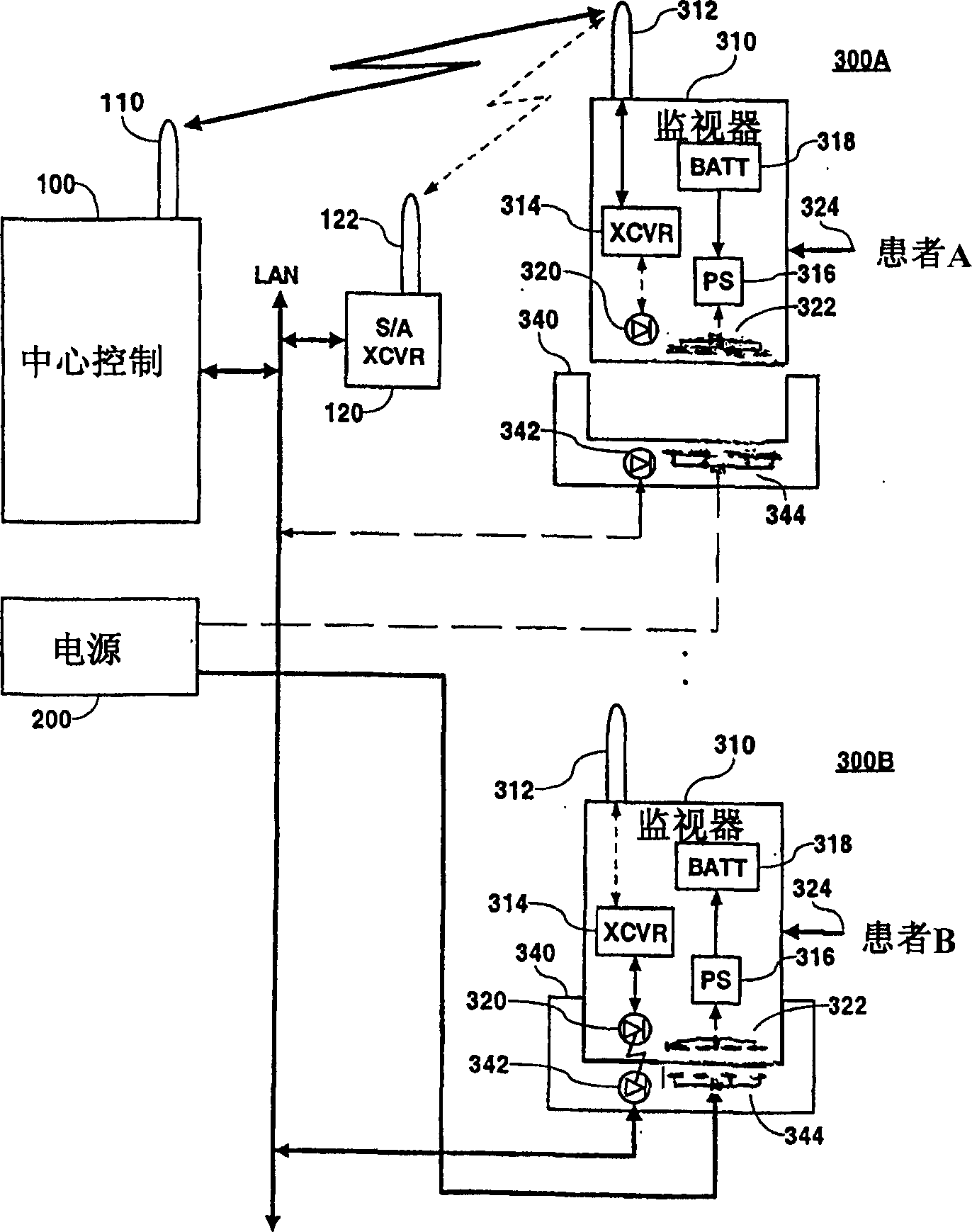
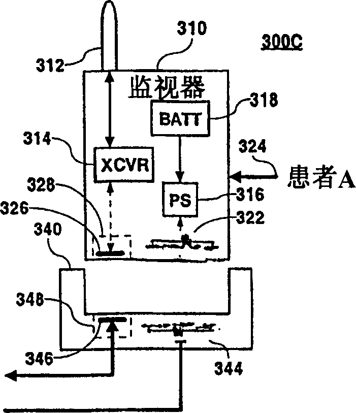
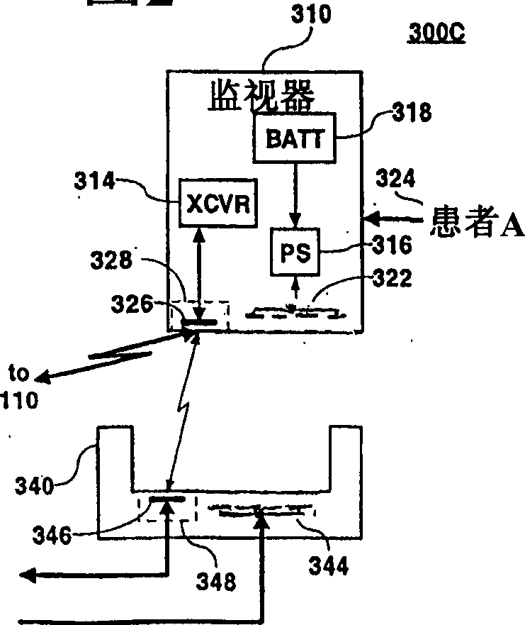
[0017] Known systems use a magnetic assembly comprising a conventional transformer core with a uniform magnetic cross-sectional area to transmit power across an interface between two separable elements comprising a power source and a device to be powered. This could include, for example, two "C-shaped" cores placed close to each other to form a C-C transformer with two gaps in the two legs of the C-C transformer at the interface between the source and powered equipment, or Alternatively, two halves of a conventional "pot-shaped" core assembly may be included with the mating surfaces of the halves at the interface. In any of the above examples, the gap at the interface will be filled by plastic or other material comprising the housing or housing of the power source and powered device, hereinafter referred to as "housing material".

[0018] The main disadvantage of this method is that the substantially constant magnetic cross-sectional area of ​​the core results in a much smalle...


PUM


Abstract

An electrically isolated combined power and signal coupler is usable for a porta ble medical monitoring device (310) attachable to a patient (A,B) in a medical e nvironment. A power coupling system transfers power between a power source and a powered device (310) separated by a physical and electrical isolation barrier. The system comprises a power coupler including in a first device (310), a first section of a magnetic circuit including a first core section (322) of magnetical ly permeable material of cross-sectional area larger at an isolation barrier int erface than within a first winding located on the first core section. The first section of magnetic circuit being suitable, in a docking mode (300B), for positi oning adjacent to a second section of magnetic circuit (344) in a second device (340) to form a magnetic circuit used to transfer power between said first and s econd device. The second section of magnetic circuit including a second core sec tion with a second winding magnetically coupling with the first winding via the completed magnetic circuit in the docking mode for the power transfer. The first core section comprises at least one planar core section at the isolation barr r interface for positioning adjacent to a corresponding substantially planar cor e section of said second section of magnetic circuit at the isolation barrier in terface to form the magnetic circuit without a device containing the second sect ion of magnetic circuit enveloping a significant portion of the substantially pl anar core section.

Description

[0001] This is a formal application of Provisional Application Serial No. 60 / 394,393 filed July 8, 2002 by C.M. Kelly et al. field of invention [0002] The present invention relates to a power supply and signal coupler for a portable medical monitoring instrument designed for connection to a patient in a medical environment. Background of the invention [0003] An electrical transformer incorporating a core of magnetic material, using the inductive coupling of the windings, is used to transfer power from one circuit to another while, in addition to increasing or decreasing the output AC voltage level, maintaining a current flow between the two circuits ( galvanic) insulation. For power supply equipment that comes into contact with people, electrical insulation is required to provide safety and avoid electric shock. Typical transformers use insulating material, such as winding insulators or plastic bobbins, between the windings and the core to prevent them from touching and...

Claims


Application Information

Patent Timeline
Patent Type & Authority Applications(China)
IPC IPC(8): H02J7/00H02J7/02H02J13/00H04B1/38
CPCH02J7/025H02J7/0021H02J13/0086H02J13/0096H04B1/3883H04B1/3816H02J7/0027H02J13/0075Y04S20/221Y02B70/3216H02J2310/12H02J13/00004H02J13/00028Y02B70/30H02J13/00022H02J50/10H02J50/70
Inventor 约翰·肯尼斯·菲奇克利福德·马克·凯利
Owner DRAEGER MEDICAL SYST INC
Why Eureka
Try Eureka