A large-scale mimo transmission method and device

A first-time, sub-frame technology, applied in the direction of error prevention/detection through diversity reception, error prevention/detection using return channel, etc., can solve the problem of inability to meet cell orthogonality, occupying time-frequency resources, and aggravating downlink measurement. RS difficulty and other issues

Active Publication Date: 2019-08-09
SHANGHAI LANGBO COMM TECH CO LTD
View PDF4 Cites 0 Cited by
  • Summary
  • Abstract
  • Description
  • Claims
  • Application Information

AI Technical Summary

Problems solved by technology

Due to the large number of antenna ports in MassiveMIMO (the number of traditional CSI-RS ports is not more than 8), the downlink measurement RS may occupy most of the time-frequency resources in the subframe-and thus cannot satisfy the orthogonality between cells
Furthermore, in eIMTA transmission, the available subframes of the downlink measurement RS change with the dynamically configured UL / DL frame structure, further exacerbating the difficulty of downlink measurement RS configuration

Method used


Image

  • A large-scale mimo transmission method and device
  • A large-scale mimo transmission method and device
  • A large-scale mimo transmission method and device

Examples


Embodiment 1

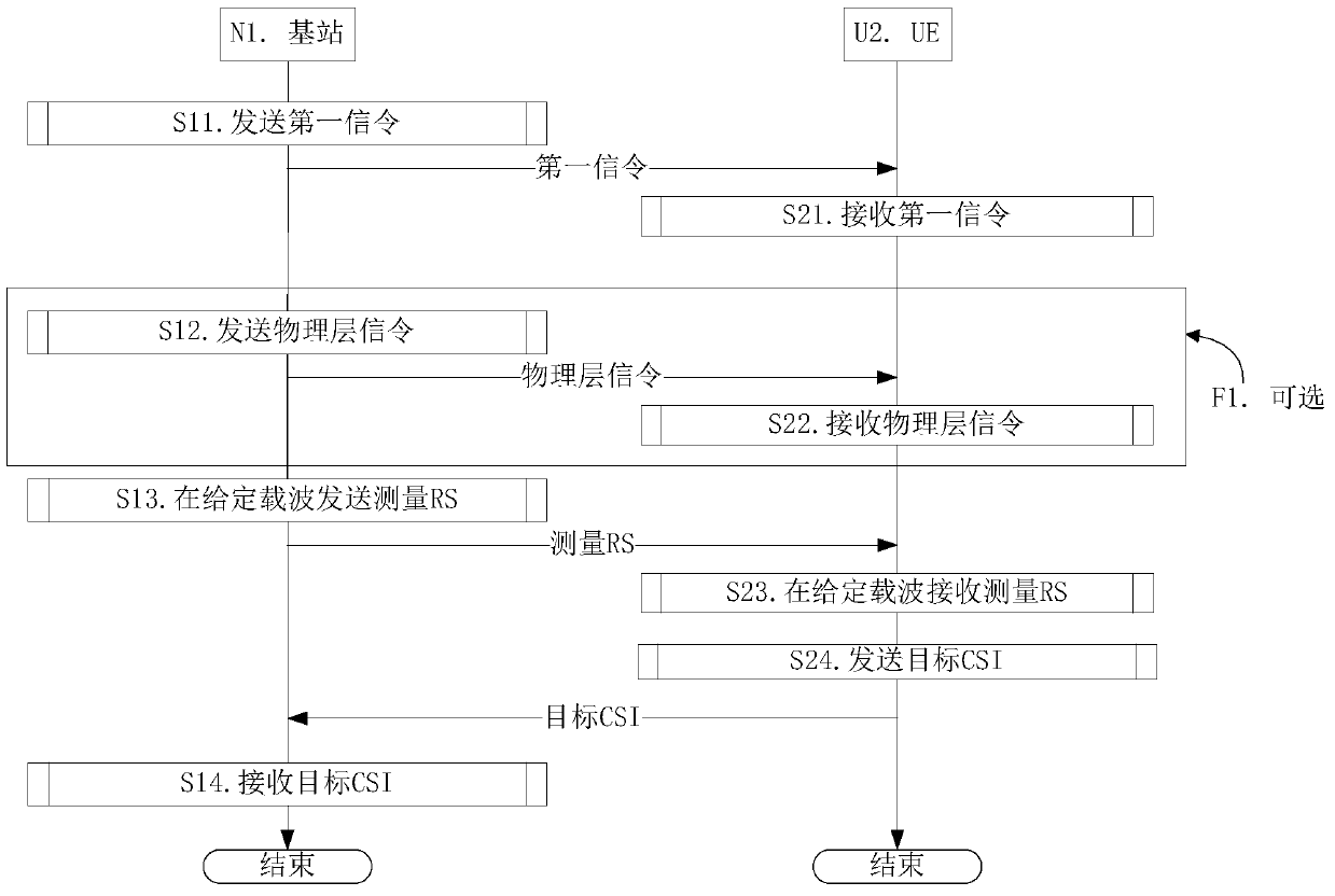
[0070] Embodiment 1 is a CSI feedback flow chart, as attached figure 2 shown. attached figure 2 In , the base station N1 is the serving base station of the UE U2. The steps identified in box F1 are optional steps.

[0071] For the base station N1, in step S11, send the first signaling to indicate the first subframe set; in step S13, on the given carrier, send the measurement RS on the downlink subframe in the first subframe set; in step S14 In the method, target CSI is received, and reference resources of the target CSI include the measurement RS. For UE U2, in step S21, the first signaling is received to determine the first subframe set; in step S23, on a given carrier, the measurement RS is received on the downlink subframe in the first subframe set; in step S24 In, the target CSI is sent, and the reference resource of the target CSI includes the measurement RS.

[0072] In Embodiment 1, the given carrier is composed of consecutive time windows in the time domain, and...

Embodiment 2

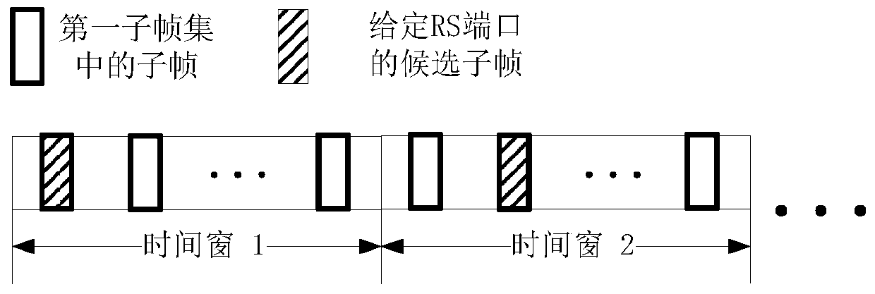
[0077] Embodiment 2 is a schematic diagram of the first subframe set, as shown in the attached image 3 shown. attached image 3 In , the squares marked with bold lines are subframes in the first subframe set, and the squares marked with oblique lines are candidate subframes for a given RS port.

[0078] For the base station, first send the first signaling to indicate the first subframe set; then on a given carrier, send the measurement RS on the downlink subframe in the first subframe set; then receive the target CSI, the reference resource of the target CSI Include the measurement RS. For UE U2, first receive the first signaling to determine the first subframe set; then on a given carrier, receive the measurement RS on the downlink subframe in the first subframe set; then send the target CSI, the reference of the target CSI A resource comprises the measurement RS.

[0079] In Embodiment 2, the given carrier is composed of consecutive time windows in the time domain, and ...

Embodiment 3

[0082] Embodiment 3 is a schematic diagram of the first subframe set in the TDD UL / DL frame structure scenario, as shown in the attached Figure 4 shown. attached Figure 4 In , the squares marked with bold lines are subframes in the first subframe set, and the squares marked with oblique lines are candidate subframes for a given RS port.

[0083] For the base station, first send the first signaling to indicate the first subframe set; then send the eIMTA signaling to indicate the downlink subframe of the given carrier within the configuration period of the eIMTA signaling; then on the given carrier, in Sending the measurement RS on the downlink subframes in the first subframe set; then receiving target CSI, where reference resources of the target CSI include the measurement RS. For UEU2, first receive the first signaling to determine the first subframe set; then receive the eIMTA signaling to determine the downlink subframe of the given carrier within the configuration perio...


PUM


Abstract

Provided are a base station, and a massive MIMO transmission method and device for a UE. In step one, the base station transmits a first signaling indicating a first sub-frame set; in step two, transmitting a measurement RS on the carrier wave in downlink sub-frames that belong to the first sub-frame set; in step three, receiving a target CSI, the reference resources of the target CSI comprising the measurement RS. The measurement RS comprises M RS interfaces. A given RS interface appears in the downlink sub-frames of S candidate sub-frames in each time window, the S candidate sub-frames belonging to the first sub-frame set. The position of the S candidate sub-frame in the time window is time-varying. The solution of the present invention prevents the problem in which a certain RS interface cannot be transmitted due to a certain sub-frame being configured as uplink by a passive signaling in an eIMTA environment. Additionally, the present invention utilizes as much as possible existing LTE designs and maximizes the compatibility with existing systems.

Description

technical field [0001] The invention relates to a channel state measurement and feedback scheme in the technical field of mobile communication, in particular to a downlink channel state measurement and feedback scheme in a mobile communication system using Massive Multiple Input Multiple Output (MIMO) technology. Background technique [0002] 3GPP (3rd Generation Partner Project, third generation partnership project) R (Release, version) 12 introduced eIMTA (enhanced Interference Management Traffic Adaptation, enhanced interference management service adaptation) technology, that is, for TDD (Time Division Duplex, Time division duplex) frame structure, which can adjust the TDD frame structure through dynamic signaling, and the adjustment period is one of {10, 20, 40, 80} ms (millisecond, millisecond), and the possible TDD frame structure includes # defined in LTE# 0 to 6 total 7 kinds of TDD UL (Uplink, uplink) / DL (Downlink, downlink) frame structure. The dynamic signaling (...

Claims


Application Information

Patent Timeline
Patent Type & Authority Patents(China)
IPC IPC(8): H04L1/06H04L1/16
CPCH04L1/06H04L1/16
Inventor 张晓博
Owner SHANGHAI LANGBO COMM TECH CO LTD
Why Eureka
Try Eureka